A-188-1 BBD Module
A-188-1 online tutorials by Raul Pena:
A-188-x BBD Basics: http://www.youtube.com/watch?v=G8fKvbutgds
A-188-1 part 1: http://www.youtube.com/watch?v=m3QXgRBdptQ
A-188-1 part 2: http://www.youtube.com/watch?v=nh2o7H5UE8E
A-188-1 part 3: http://www.youtube.com/watch?v=PulaMQLm13w
A-188-1 Online
review: www.electro-music.com
|
|
|
|
 |
| Vintage Edition Die Vintage-Versionen sind Auslauftypen, Verkauf solange Vorrat reicht The vintage versions are running out, sale while stocks last |
|
BBD module scheme
Module
A-188-1 is a so-called Bucket Brigade Device module (abbr.
BBD). BBDs have been used to delay audio signals before digital delays dethroned
the BBD based effect units. But BBDs have some very unique advantages (or
disadvantages dependent on the point of view) over the digital counterpart which
result from the special properties of the BBDs. BBD circuits can be treated as a
chain of Sample&Hold units (S&H) which pass on their voltages to the
next S&H in the chain at each clock pulse. A more detailed explanation
including the different types of BBDs can be found in following chapter.
In any case the sounds generated by module A-188-1 are very special. Typical applications are: Flanger, Chorus, Analog Delay or Karplus/Strong synthesis. But as the A-188-1 has a lot of very unique features (voltage controlled clock rate / delay time with extreme range, polarity switches for the CV inputs, feedback and BBD out/mix, clock and CV output of the high speed VCO, BBD clock input, feedback insert, feedback up to self-oscillation) a lot of unusual applications can be realized with the module (e.g. delay controlled by ADSR, envelope, random or sequencer with positive or negative effect). The A-188-1 also has no built-in anti-alisaing filter in order not to limit the possibilities of the module. For this the CV out is intended.
A
more detailed description of the module can be found in the user's manual
![]() A1881_man.pdf.
A1881_man.pdf.
Originally A-188-1 was developed for BBD curcuits with 1024 or 2048 stages as these circuits are still in production. Bur
we found a limited quantity of normally obsolete BBD devices with 128, 256, 512 and 4096 stages (MN3006, MN3009/3209, MN3204, MN3005). These are more expensive than the two standard circuits with 1024 and 2048 stages. Therefore the module versions with 128, 256, 512 or 4096 stages are more expensive and available only while stocks last. The BBD type used in the module is indicated by a dot at the front panel. These are the names of the different versions:- A-188-1X with 128 stages BBD (MN3006/MN3206)
A-188-1Y with 256 stages BBD (MN3009/MN3209)nicht mehr lieferbar / no longer available- A-188-1A with 512 stages BBD (MN3004/MN3204), available only as long as quantities of MN3004/MN3204 last geringer Bestand / low stock !
- A-188-1B with 1024 stages BBD (MN3007/MN3207/BL3207)
- A-188-1C with 2048 stages BBD (MN3008/MN3208/BL3208)
- A-188-1D with 4096 stages BBD (MN3005/MN3205)
For the BBD circuits with 128 and 4096 stages the first version of the A-188-1 cannot be used without modifications (additional electronic parts and wires, interrupted pcb tracks). The revised version of the module is delivered since about June 2006 and contains several jumpers to select the desired BBD circuit. If desired we are able to modify the first version of the module for the BBD with 4096 or 128 stages (additional charge).
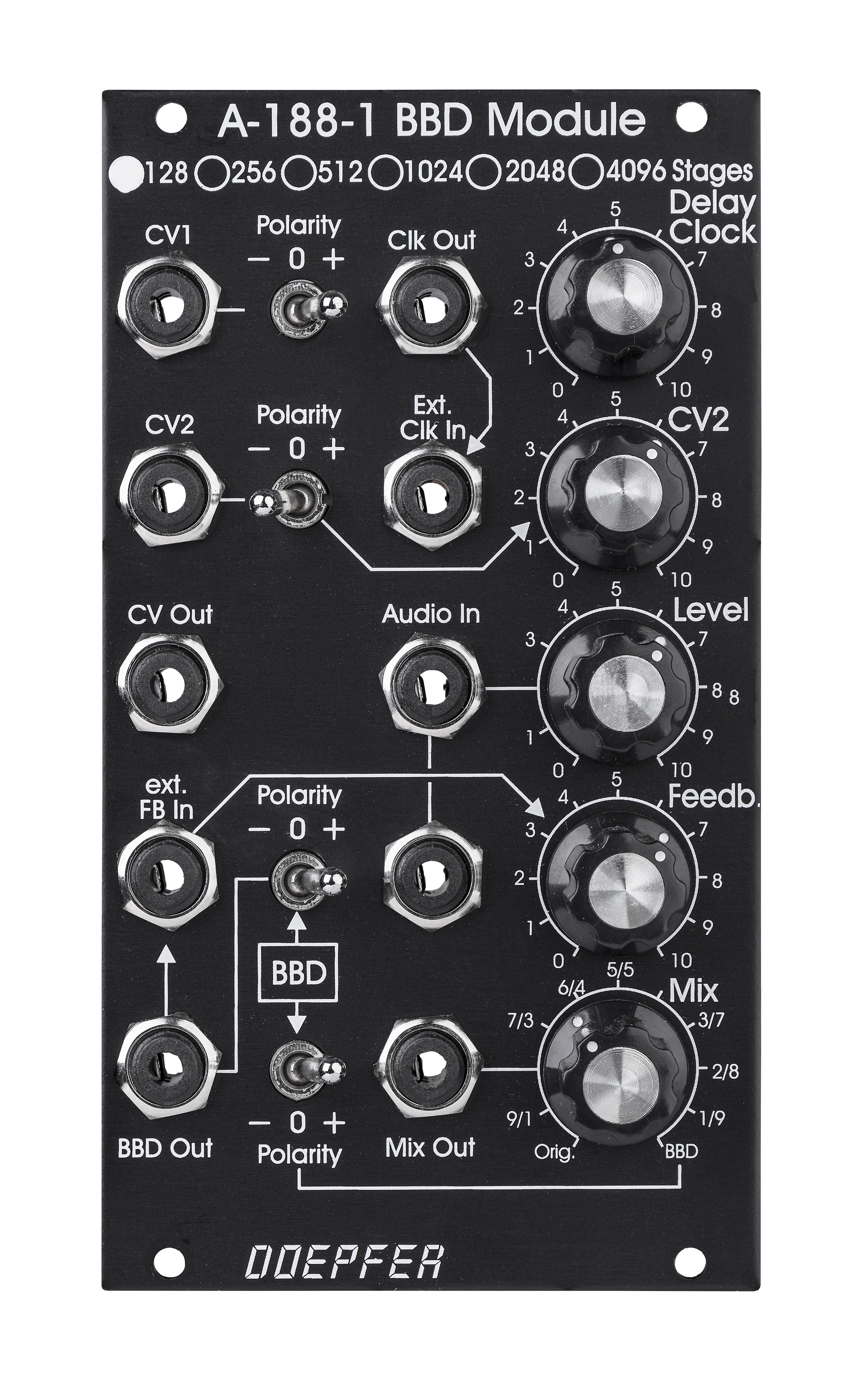
The above pictures shows the front panel (version 2) and the scheme of the BBD module. These controls and in/outputs are available:
- High speed VCO (HSVCO) section:
- manual delay control
- delay CV input (CV1) without attenuator (about 1V/oct) and polarity switch (negative/off/positive)
- delay CV input (CV2) with attenuator and polarity switch (negative/off/positive)
- turning the manual delay knob clockwise or an increasing the external CV with polarity switch in positive position increases the clock and consequently decreases the delay time (similar to a VCF or VCO, especially because of Karplus-Strong synthesis applications)
- clock output (e.g. to control another BBD, SC-Filter or delay module)
- CV output (e.g. to control a VCF that follows the BBD clock), this voltage is composed of the manual delay control, CV1 and CV2
- BBD/audio section:
- standard versions of the module: 1024 or 2048 stage BBD (choice at order, a mark at the front panel identifies the type of BBD, similar to A-138a/b)
- special versions of the module: 128, 256, 512 or 4096 stage BBD (additional charge, available only while stocks of these special BBD chips last)
- delay range for 1024 stage BBD module: ~ 2.5 ms to ??? (corresponds to max. a clock frequency of ~ 200 kHz)
- delay range for 2048 stage BBD module: ~ 7 ms to ??? (corresponds to max. a clock frequency of ~ 150 kHz)
- the delay ranges for the 128, 256, 512 and 4096 stage versions can be found in the user's manual A1881_man.pdf.
- the max. delay time (???) is not specified as it depends upon the desired quality of the delayed audio signal. The signal becomes more and more poor as the clock frequency is reduced (please refer to the corresponding note below and listen to the audio examples for details)
- external clock input (used to control the module e.g. from an external HSVCO or from another BBD module). The socket is normalled to the output of the internal clock oscillator.
- two audio inputs (connected as a miniature multiple) with attenuator
- BBD output (raw delayed output without original signal, e.g. for external feedback control via other A-100 modules, e.g VCA or VCF), the BBD output is affected by the feedback polarity switch to obtain the polarity function even for external feedback loops
- manual feedback control
- feedback polarity switch (positive/off/negative), affects even the BBD output socket
- external feedback input (the socket is normalled to BBD output)
- BBD signal polarity switch (positive/off/negative)
- mix control (relation between original signal and positive or negative BBD signal)
- mixed audio output
Links to some audio examples are available below (with 2048 and 1024 stage BBD devices). The main difference between the two types of BBDs is the delay time range. The maximum clock frequency mentioned in the data sheet of the 2048 stage BBD is 100kHz. This leads to a minimum delay time of about 10ms. But we found that the device is able to operate even a bit beyond this spec (up to ~ 150kHz) causing a minimum delay time of about 7ms. The maximum clock frequency mentioned in the data sheet of the 1024 stage BBD is 200kHz. This leads to a minimum delay time of about 2,5ms. Overclocking is not possible for the 1024 stage BBD.
The maximum (useful) delay time is hard to define. The output becomes more and more crunchy as the clock frequency goes down because the number of samples per second taken from the original signal decreases as the clock frequency is reduced. But this is only one aspect. Indeed several effects occur simultaneously:
- kind of bit crunching because of the increasing time between samples taken from the audio signal
- aliasing effect as the sample rate becomes less than twice the max. audio frequency
- BBD losses: the BBDs are not specified for clock frequencies less than 10 kHz (this value is valid for both 1024 and 2048 stage BBDs). The BBDs can be treated like a chain of sample&hold units with very small capacitors (the capacitors are integrated on the BBD chip). Clock frequencies below 10kHz cause voltage losses as the holding times of the S&Hs are no longer sufficient to pass on the voltages to the succeeding stage without errors/losses.
The sound effects of low clock frequencies can be heard in the audio examples below.
The first section of MP3 examples is made with a 2048 stage BBD device. The maximum clock frequency mentioned in the data sheet of the 2048 stage BBD is 100kHz. This leads to a minimum delay time of about 10ms. But we found that the device is able to operate even a bit beyond this spec (up to ~ 150kHz) causing a minimum delay time of about 7ms.
Two different audio sources are used for the examples:
- BBD_Source_1.mp3:
a short sample recorded with the A-112 (original signal #1 without BBD effect for reference)
BBD_Source_2.mp3: an 8 note sequence made with A-100 modules: A-110 + A-105 + A-140 controlled by a MAQ16/3 (original signal #2 without BBD effect for reference)
For both audio signals a standard flanger appication was made: triangle output of a LFO is used to control the clock CV input of the BBD module, short delay time/high clock rate, medium resonance.
For the first audio signal an example with an envelope follower was made. The A-112 output is processed by an A-119. The envelope output of the A-119 is used to control the clock CV input of the BBD module. In addition the manual clock rate is reduced by hand during the example. At the end of the example the sound becomes more and more "destroyed" as the clock rate goes below the value that is specified for the BBD circuit. In addition at the end of the example the clock frequency can be heard as it is now in the audible range (the input signal is scanned with the audible clock rate):
In the last example the second audio source is used and the clock rate is changed manually over the whole range and back again. Additionally the resonance/feedback is lowered a bit by hand during the delay times.
The next mp3's show some examples of the Karplus-Strong synthesis. The patch is the same for all examples:
Karplus-Strong patch
The digital noise signal of the A-117 is processed by a VCA (A-131) that gets it's envelope from an envelope generator (A-140). The output of the VCA is the audio input of the BBD module. A sequencer MAQ16/3 that is used to generate a simple sequence. The gate output of the MAQ16/3 is triggering the gate input of the A-140, the CV output of the MAQ16/3 is controlling the CV clock of the BBD module.
The first three examples show the patch at different settings of the manual clock control of the BBD module (no parameter is changed during the example in question):
In the next example the Resonance (or feedback) control of the BBD module is increased manually (all other parameters remain unchanged):
In the following example the Decay of the Envelope generator (A-140) is increased manually (all other parameters remain unchanged)::
In the last example the Clock rate of the digital noise (A-117) is increased manually (all other parameters remain unchanged)::
With suitable modules all the manually changed parameters can be voltage controlled too (e.g. external VCA in the feedback loop of the BBD module, A-141 or A-142 instead of A-140, external clock for the A-117, e.g. from an A-110 or A-111). And of course another sound source can be used (e.g. "analog" blue/red noise from A-118, "2 oscillators" or "6 oscillators" signal of A-117, VCO, external signal, looped A-112 sample and so on).
For the second section of examples the module has been modified so that a 1024 stage BBD device could be used. The maximum clock frequency mentioned in the data sheet of the 1024 stage BBD is 200kHz. This leads to a minimum delay time of about 2,5ms. One of the audio sources of the above examples (BBD_Source_1.mp3) is also used for the examples with the 1024 stage BBD module
The first two examples show again kind of a flanger application (triangle output of a LFO is used to control the delay CV input of the BBD module). In the beginning only the original signal appears. Then the delayed signal is added manually without feedback (mix control is changed from 0% to 50%, feedback control = 0). Then the feedback is increased manually. The only difference between the two examples is the feedback polarity:
- BBD_1024_Flange_LFO_Feedback_1.mp3 (feedback switch set to "+")
- BBD_1024_Flange_LFO_Feedback_2.mp3 (feedback switch set to "-")
The next example shows the full delay range of the 1024 stage BBD module that is possible with the internal HSVCO. The delay time is changed manually from minimum to maximum (manual delay control is changed from ccw to cw by hand). Feedback is set to medium.
In the last example the delay time is controlled by an analog sequencer (2xA-155 + A-154). Feedback is set to medium. Same audio source as for the other examples.
The green line shows the behaviour of a perfect HSVCO, the red line the "real" HSVCO of the BBD module
Tiefe/Depth: 60 mm (gemessen ab der Rückseite der Frontplatte / measured from the rear side of the front panel)
Strombedarf/Current: +80mA (+12V) / -50mA (-12V)
Standard Versions :
A-188-1X (128 stages, MN3006/MN3206) 175.00 Euro, only as long as quantities of MN3006/MN3206 last
A-188-1A (512 stages, MN3004/MN3204) 190.00 Euro, only as long as quantities of MN3004/MN3204 last geringer Bestand / low stock !
A-188-1B (1024 stages) 155.00 Euro, standard version, keine Lieferbeschränkungen / no delivery limitations
A-188-1C (2048 stages) 155.00 Euro, standard version, keine Lieferbeschränkungen / no delivery limitations
A-188-1D (4096 stages, MN3005/MN3205) 195.00 Euro, keine Lieferbeschränkungen / no delivery limitations
A-188-1? without BBD circuit, unadjusted 135.00 Euro,
For the version without BBD circuit the final adjustment has to be carried out by the customer as it's possible only with the BBD circuit used in the module.
Electronic experience and measuring equipment (digital multimeter, oscilloscope, frequency meter) required. The following document describes the A-188-1 adjustment procedure: A1881_adjustment.pdf
Vintage Editions
:
10.00 Euro Aufpreis / Euro 10.00
surcharge for each type
The prices in US$
depend upon the exchange rate between Euro and US$ at the payment day.