A-107 Multitype Morphing Filter
nicht mehr lieferbar / no longer available


click to enlarge


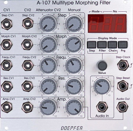
  • Bedienungselemente:

    Manual Step (Drehpotentiometer)
    Step CV (Drehpotentiometer)
    Manual Morph. (Drehpotentiometer)
    Morph. CV (Drehpotentiometer)
    Manual Frequency (Drehpotentiometer)
    Frequency CV (Drehpotentiometer)
    Man. Resonance (Drehpotentiometer)
    Resonance (Drehpotentiometer)
    Man. Amplitude (Drehpotentiometer)
    Amplitude CV (Drehpotentiometer)
    Audio In  (Drehpotentiometer)
    Step (Taster)
    Filter (Taster)
    Chain (Taster)
    Program (Taster)
    Value (Endlos-Drehgeber)
    3-stelliges LED-Display

  • Ein/Ausgänge (Buchsen):

    Step CV 1
    Step CV 2
    Morph. CV 1
    Morph. CV 2
    Frequ. CV 1
    Frequ. CV 2
    Resonance CV1
    Resonance CV2
    Amplitude CV1
    Amplitude CV2
    Audio In
    Audio Out 
    Step Clock
    Step Reset

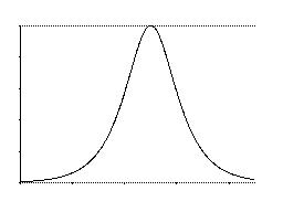
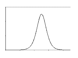
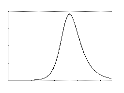
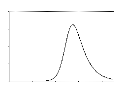
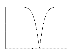
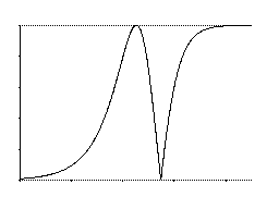
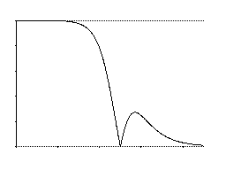
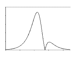
Das Modul A-107 ist ein völlig neuartiges spannungsgesteuertes Filter, das 36 verschiedene Filtertypen beinhaltet: verschiedene Tiefpässe, Hochpässe, Bandpässe, Notch-Filter, Allpässe und spezielle Filterverläufe, die - zumindest bisher noch - keine gängige Bezeichnung besitzen. Die Filtertypen sind in der Grafik am Ende dieser Seite in Form von Frequenzgang-Kurven angegeben. Die Filter sind in zwei Gruppen zu je 18 Filtern organisiert. Zwischen den verschiedenen Filter-Typen ist innerhalb einer Gruppe ein stufenloser Übergang ("Morphing") , aber auch ein harter Übergang (umschalten) möglich.
Das Filter wurde inspiriert vom ERWIK Musikelektronik Multimode Filter, das wiederum auf dem Filter basiert, welches im Oberheim Matrix 12 bzw. Xpander zum Einsatz kam (Danke an Jesper Erwik Johansson für seine Unterstützung und sein Einverständnis, dass wir seine Idee in unserem A-107 verwenden). Die Möglichkeiten des A-107 gehen jedoch über die erwähnten Filter weit hinaus, da eine Reihe neuer, bisher nicht realisierter Filtertypen verfügbar sind und ausserdem ein stufenloser Übergang (Morphing) zwischen den Filtertypen möglich ist. Der Übergang zwischen den Filtern wird von 2 Parametern gesteuert:

  • Filtertyp (bezeichnet mit Step)

  • Umblend-Geschwindigkeit (bezeichnet mit Morph)

Für beide Parameter ist jeweils ein manueller Regler, ein Steuerspannungseingang mit Abschwächer und ein Steuerspannungseingang ohne Abschwächer verfügbar.
Die 36 zur Verfügung stehenden Filtertypen können in verschiedenen Reihenfolgen oder Ketten (bezeichnet mit Chains) mit einer Länge von je 32 Schritten hintereinander angeordnet werden, so dass sie in dieser Folge beim Verändern der Steuerspannung von 0...+5V "durchfahren" werden. 64 dieser Chains können vom Benutzer frei programmiert und im nicht-flüchtigen Speicher des Moduls abgelegt werden. Hierzu dienen folgende Bedienungselemente:

  • Step: Taster zur Anwahl einer Stufe (1-32) innerhalb der Filtersequenz in Kombination mit dem Value-Drehgeber
  • Filter: Taster zur Anwahl der Nummer des Filters (1..36) für die aktuelle Stufe in der Sequenz in Kombination mit dem Value-Drehgeber
  • Chain: Taster zur Anwahl einer Filter-Kette/Sequenz (1...64) in Kombination mit dem Value-Drehgeber
  • Program: Taster zur Speicherung aktuellen Filter-Kette/Sequenz auf einem Speicherplatz (1...64) des nicht-flüchtigen Speichers
  • Value (Endlos-Drehgeber, Encoder) zur Veränderung des mit den Tastern angewählten Parameters
  • 3-stelliges Display (die erste Stelle gibt an ob gerade der Wert für Step "S", Filter "F" oder Chain "C" angezeigt wird, die zweite und dritte Stelle zeigen den aktuellen Wert)

Zusätzlich ist eine "clocked" Betriebsart verfügbar, bei der die Filterstufen der momentan angewählten Filterkette über ein externes Clock-Signal (Buchse mit der Bezeichnung Step Clock) fortlaufend durchgeschaltet werden können. Ein positives Trigger-Signal am Reset-Eingang (Buchse mit der Bezeichnung Step Reset) schaltet auf den den ersten Filter der Filterkette zurück. Hiermit kann die Filterumschaltung beispielsweise synchron zu einer Sequenz erfolgen.

Der bei jedem VCF übliche Frequenzregler und zwei Steuereingänge für die Filterfrequenz (davon einer mit Abschwächer) stehen natürlich auch zur Verfügung.
Zusätzlich ist auch spannungsgesteuerte Resonanz verfügbar (manueller Regler, ein Steuerspannungs-Eingang mit Abschwächer und ein Steuerspannungs- Eingang ohne Abschwächer).
Bei den Filtertypen der Gruppe 1 (Filter 1...18) ist Eigenschwingung möglich, bei den Filtern der Gruppe 2 (19...36) nicht.

Ausserdem steht ein Ausgangs-VCA zur Verfügung, ebenfalls mit manueller Einstellung der Verstärkung, Steuerspannungs-Eingang mit Abschwächer und Steuerspannungs- Eingang ohne Abschwächer.

Das Filterdesign ist 100% analog (CEM-Filterbaustein), nur die Morphing-Steuerung und die Speicherverwaltung übernimmt ein Microcontroller.

Hinweis: Der Übergang von einer Filtergruppe (1...18 / 19...36) zu anderen ist aus technischen Gründen nur hart möglich (Umschaltung von Kondensatoren). Weiches Überblenden (Morphing) ist daher nur innerhalb einer Filtergruppe (d.h. innerhalb der Filter 1...18 oder 19...36) möglich. Werden nacheinander 2 Filter angewählt, die zu unterschiedlichen Filtergruppen gehören, ist wegen der Umschaltung der Kondensatoren ein kurzes Klick-Geräusch zu hören. Um in jedem Fall weiche Übergänge sicherzustellen, dürfen daher innerhalb einer Kette (Chain) nur Filter aus der selben Filtergruppe verwendet werden. 

Die deutsche Bedienungsanleitung ist als PDF-Datei auf unserer Website verfügbar: A107_Anl.pdf

Das Modul ist leider nicht mit blauem Display lieferbar, da das verwendete integrierte Display (Controller und 3-fach-Display als eine Einheit, Hersteller: Liteon) bisher nicht in blau erhältlich ist.


click to enlarge


  • Controls:

    Manual Step (rotary potentiometer)
    Step CV (rotary potentiometer)
    Manual Morph. (rotary potentiometer)
    Morph. CV (rotary potentiometer)
    Manual Frequency (rotary potentiometer)
    Frequency CV (rotary potentiometer)
    Man. Resonance (rotary potentiometer)
    Resonance (rotary potentiometer)
    Man. Amplitude (rotary potentiometer)
    Amplitude CV (rotary potentiometer)
    Audio Input Level (rotary potentiometer)
    Step (button)
    Filter  (button)
    Chain  (button)
    Program (button)
    Value (endless rotary encoder)
    3 digit LED display

  • In/Outputs (jack sockets):

    Step CV 1
    Step CV 2
    Morph. CV 1
    Morph. CV 2
    Frequ. CV 1
    Frequ. CV 2
    Resonance CV1
    Resonance CV2
    Amplitude CV1
    Amplitude CV2
    Audio In
    Audio Out 
    Step Clock
    Step Reset


Module A-107 is a completely new voltage controlled filter that has available 36 filter types: different versions of low pass, high pass, band pass, notch, all pass and filters with new response curves that have no name up to now. The frequency response curves of the 36 filters available in the A-107 are shown in the graphics at the end of this page. The filters are organized in two groups of 18 filters each. The transition between different filter types within one group can be soft (morphing) or hard (switching).
The filter was inspired by the ERWIK Musikelektronik Multimode Filter, which is based on the filter used in the Oberheim Matrix 12 resp. Xpander (thanks to Jesper Erwik Johansson for his assistance and permission to use his idea in our A-107 module). The possibilities of the A-107 go far beyond these filter designs as a lot of new filter types are available and the transition between filters can be soft (morphing) or hard (switching) and the filters can be arranged in 64 different voltage controlled filter chains.

The transistion between the different filter types is controlled by two parameters:

  • Filter Step (marked Step at the front panel)

  • Morphing Time (marked Morph at the front panel)

For both parameters manual control, one CV input with attenuator and one CV input without attenuator are available.

The 36 filter types can be arranged in filter chains (resp. filter sequencer or filter orders) so that this sequence of filters is passed through while the control voltage changes from 0...+5V. Each chain consists of 32 steps. 64 filter chains can be programmed by the user and stored in the non-volatile memory of the module. The following controls are used to program the filter chains:

  • Step: button to address the desired step (1...32) within the filter chain in combination with the value encoder
  • Filter: button to select the filter number (1...36) that is assigned to the current step within the chain in combination with the value encoder
  • Chain: button to select one of the filter chains (1...64) in combination with the value encoder
  • Program: button to store the current filter chain in one of the non-volatile memories (1...64) in combination with the value encoder
  • Value: endless rotary encoder to change the parameter selected with the buttons
  • 3 digit Display (the first digit indicates of the current value shows Step "S", Filter "F" or Chain "C", the second and third digit display the number)

Additionally a "clocked" mode is available. This means that the steps of the currently selected filter chain are selected one after another. Each positive transition of the Clock signal calls up the next filter of the chain (jack socket marked Step Clock). A positive trigger at the Step Reset input (jack socket marked Step Reset) resets to the first filter of the current filter chain. This allows e.g. to switch between the filters of the currently selected filter chain in sync with a sequencer.

Of course the standard VCF controls are available: manual filter frequency control, one CV input with attenuator and one CV input without attenuator.
In addition voltage controlled resonance with
manual control, CV input with attenuator and CV control without attenuator are available. For the filters of the first group (1...18) self-oscillation is possible, the filters of the second group (19...36) do not feature self-oscillation.

On top of it a final VCA is available (even with manual control, CV input with attenuator and CV input without attenuator).

The filter design is 100% analog (CEM filter chip). Only the morphing control and memory managing is carried out by a microcontroller.

Remark: Because of technical reasons the transition between the two filter groups (1...18, resp. 19...36) cannot be carried out soft as capacitors have to be switched. Soft transition (i.e. morphing) is possible only within the filter group (i..e. within the filters 1...18 or 19...36). Switching between filters causes a "click" if the filters are from different groups.  

For more detailed information please look at the English user's manual A107_man.pdf

Sorry, the A-107 is not available with blue display as the integrated 3-digit display (combined controller and triple display, manufacturer: Liteon) used is not available in blue color so far.. 


Breite: 26 TE / 131.8 mm
Tiefe: 40 mm (gemessen ab der Rückseite der Frontplatte)
Strombedarf:
+200mA (+12V) / -60mA (-12V)
Width: 26 HP / 131.8 mm
Depth: 40 mm (measured from the rear side of the front panel)
Current:
+200mA (+12V) / -60mA (-12V)

Preis: 300.00 Euro
nicht mehr lieferbar
Price: 300.00 Euro
no longer available
The price in US$ depends upon the exchange rate between Euro and US$ at the payment day.


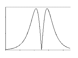
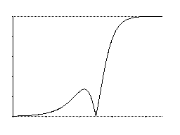
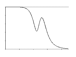
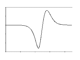
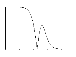
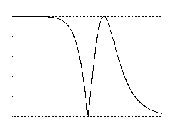
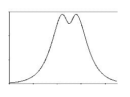
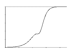
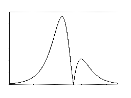
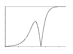
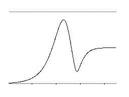
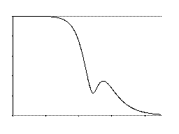
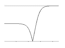
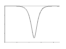
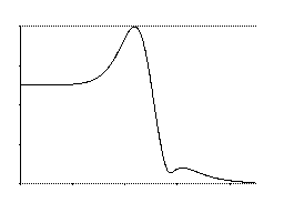
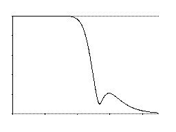
Frequenzgang für verschiedene Filtertypen (bei minimaler Resonanz)  / Frequency Response for different filter types (min. resonance)

1. Filter types available in the ERWIK and Matrix 12/Xpander filter

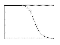
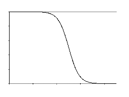
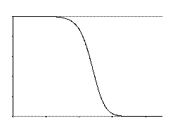
1 pole low pass (6 dB) 2 pole low pass (12 dB) 3 pole low pass (18 dB) 4 pole low pass (24 dB)

 
1 pole high pass (6 dB) 2 pole high pass (12 dB) 3 pole high pass (18 dB)  

2 pole band pass
(= 6 dB low pass + 6 dB high pass)
4 pole band pass
(= 12 dB low pass + 12 dB high pass)
asymmetric band pass 1
(= 12 dB low pass + 6 dB high pass)
asymmetric band pass 1
(= 18 dB low pass + 6 dB high pass)

notch all pass
(low frequencies attenuated)
notch + low pass 6dB low pass + all pass

2. New Filter types not available in the ERWIK and Matrix 12/Xpander filter

new #1
two band passes separated by a notch

new #2
notch + high pass (1)

new #3
low pass + shifted band pass

new #4
(soft notch + shiftet band pass)

new #5
low pass + notch

new #6
all pass (high frequencies attenuated)

new #7
"tooth" (2 displaced band passes)

new #8
(high pass with "dent")


new #9
low pass + notch + high pass

new #10
notch + high pass (2)

new #11
low pass + band pass + soft notch

new #12
low pass + soft notch + band pass

new #13
low pass (a=1) + notch + high pass (a=2)

new #14
soft notch

new #15
low pass with 2 displaced band passes with different amplitudes

new #16
low pass with shiftet band pass (lower   amplitude)

All  yellow marked filters are new ones (not available in the ERWIK/Matrix12/Xpander filters). The pictures show the most important new filter types we found so far. It is not yet fixed which filter types will be realized in the final module. Probably the 15 original Matrix/Erwik filter and the new 16 filters shown above will be available.
Pay attention: all these filter responses shown above are without resonance. Adding resonce leads to additional changes !