A-115 Audio Divider
|
|
 |
Das Modul A-115 ist ein
vierstufiger Frequenzteiler (engl. frequency divider). Die Frequenz eines Signals am
Eingang wird halbiert (halbe Frequenz = 1. Suboktave), geviertelt (1/4 Frequenz = 2.
Suboktave), usw.. Auf diese Weise erzeugt der DIVIDER vier Suboktaven (F/2 bis F/16).
Am Ausgang stellt der A-115 den Summenmix aus Original und Suboktaven bereit. Dabei
können Sie den Anteil (d.h. die Amplitude) des Originalsignals und jeder Suboktave
individuell mit einem Abschwächer einstellen. Die vom A-115 erzeugten Suboktaven sind
symmetrische Rechtecksignale sind. Am Ausgang steht ein Summenmix aus den vier
Rechtecksignalen und dem Originalsignal bereit.
Die deutsche Bedienungsanleitung ist als PDF-Datei
auf unserer Website verfügbar: ![]() A115_anl.pdf.
A115_anl.pdf.
Hinweis: In der neuen
Version des A-115 (V2 2008) ist eine zusätzliche 3-polige Stiftleiste
vorhanden, auf die eine Steckbrücke (Jumper) aufgesteckt ist. Die Stiftleiste
ist mit "JP3/Source #1" bezeichnet und befindet sich am oberen Rand
der Leiterplatte. Mit dem Jumper wird bestimmt, ob für den oberen Regler
("Orig.") das unveränderte, an der In-Buchse anliegende
Original-Signal oder das daraus abgeleitete Rechteck-Signal verwendet wird. In
der linken Position (in Richtung der Frontplatte) wird das unveränderte
Eingangssignal, in der rechten Position das daraus abgeleitete Rechtecksignal
verwendet.
Außerdem ist ein weiterer Jumper "JP2 AC/DC" verfügbar, mit dem die
Art der Kopplung des Ausgangssignals definiert werden kann. Ist der Jumper JP2
gesetzt, so ist das Signal gleichspannungsgekoppelt (DC). Diese Variante wird
z.B. dann gewählt, wenn sehr niederfrequente Signale geteilt werden (z.B. mit
einem LFO als Einganssignal). Wir der Jumper JP2 entfernt, so ist der Ausgang
wechselspannungsgekoppelt (AC). Diese Variante wird üblicherweise im
Audio-Betrieb gewählt, da das Ausgangssignal dann keinen Gleichspannungsanteil
besitzt.
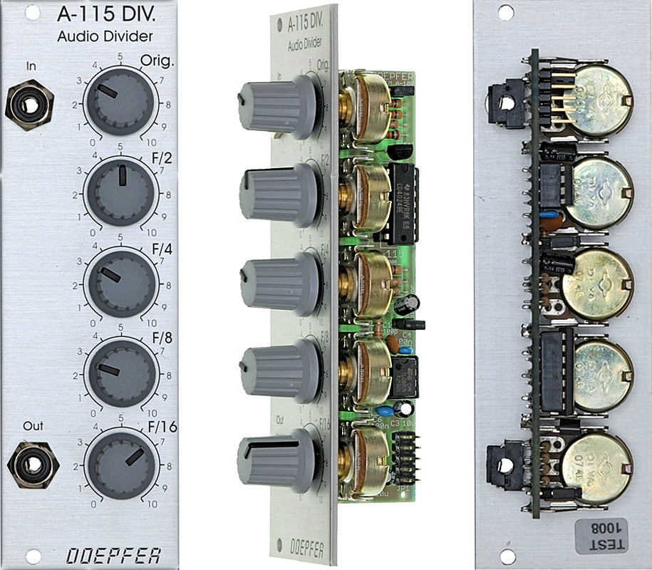
Module A-115 is a four-way frequency divider. The
frequency of a signal at the input is halved (half frequency = first sub-octave),
quartered (1/4 frequency = second sub-octave), and so on. In this way, the DIVIDER
produces four sub-octaves (F/2 down to F/16).
At the output, the A-115 produces a summed mix of the original and the four sub-octaves.
There are attenuators to control the amount (ie. Amplitude) of the original signal and
each of the sub-octaves.
Bear in mind that the sub-octaves output by the A-115 are all true square waves. At the
output there are always four square waves and the original signal available.
For more detailed information please look at the
English user's manual ![]() A115_man.pdf
A115_man.pdf
Note: The new version
of the A-115 (V2 2008) has an additional 3-terminal pin header with associated
jumper available. JP3 at the top of the pcb (labelled "Source #1") is
used to select if the original signal (i.e. the unchanged input signal of the In
socket, not converted into rectangle) or the rectangle signal (derived from the
input signal) is used for the Orig. control. In the left position of the jumper
(towards the front panel) the unchanged original signal is used. In the right
position the derived rectangle is used.
In addition another jumper "JP2 AC/DC" is available which is defines
the type of output coupling. When JP2 is installed the output is DC coupled.
This version is normally chosen when the module is used for dividing sub-audio
signals (e.g. with LFO as input). When JP2 is removed the output is AC coupled.
This is normally used for audio signals because then the output signal has no DC
offset voltage.
Breite/Width: 8TE / 8HP / 40.3 mm
Tiefe/Depth: 40 mm (gemessen ab der Rückseite der Frontplatte / measured from
the rear side of the front panel)
Strombedarf/Current: +20mA (+12V) / -10mA (-12V)
Preis/Price: Euro 70.00
The price in US$
depends upon the exchange rate between Euro and US$ at the payment day.