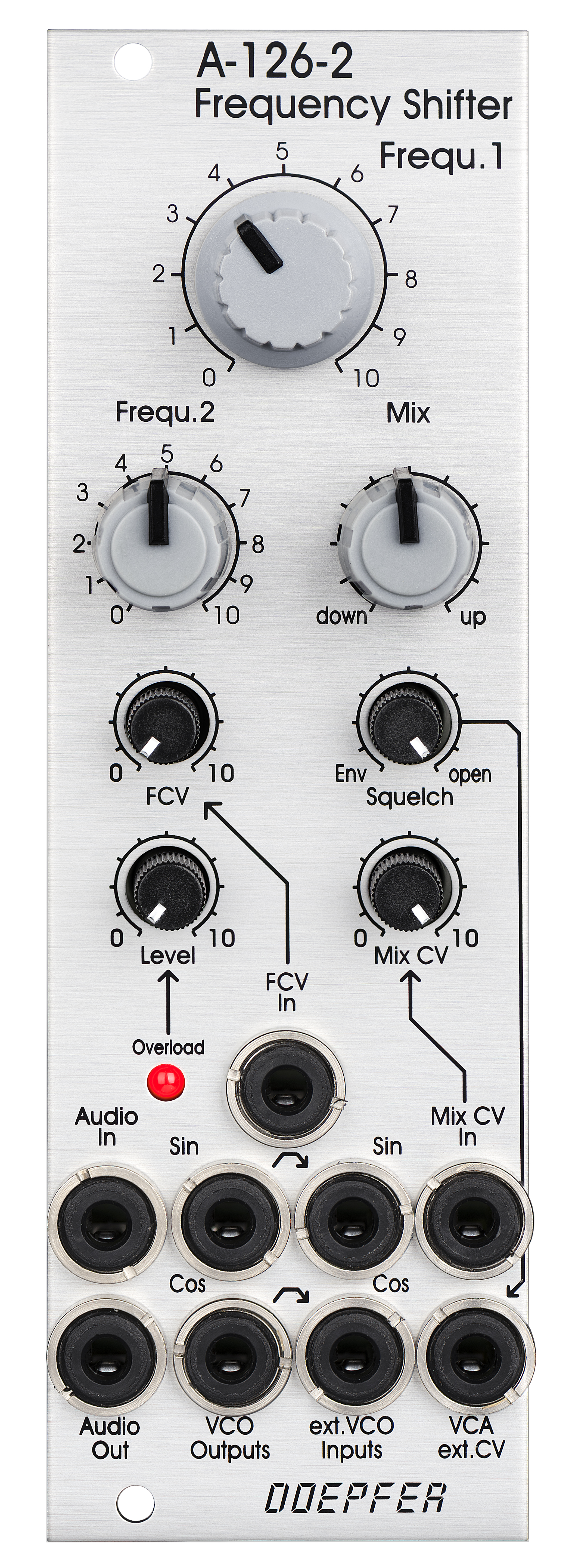
A-126-2 Voltage Controlled Frequency Shifter II
etwa ab der Mitte des Videos wird ein spezieller Feedback-Stereo-Patch des Frequency-Shifters A-126-2 gezeigt
about from the middle of the video a very special feedback stereo patch of the frequency shifter A-126-2 is shown
| click to enlarge | |
 |
|
 |
|
| Hauptmodul | Erweiterungs- modul |
 |
|
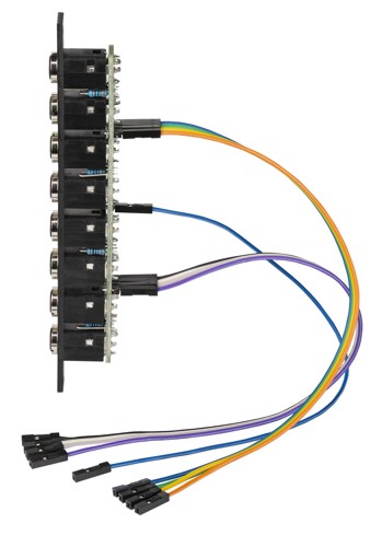
| Kabelverbindungen des Erweiterungsmoduls | |
Das Modul A-126-2 ist ein zu 100% analog aufgebauter Frequenzschieber (Frequency Shifter) für Audio-Signale. Ein Frequenzschieber verschiebt alle Frequenzen des Audio-Signals am Eingang um die gleiche Frequenz. Beträgt die Schiebefrequenz beispielsweise 200 Hz, so werden aus 1000 Hz 1200 Hz, aus 2000 Hz 2200 Hz, aus 3000 Hz 3200 Hz usw. Das Resultat ist ein völlig anderes als beim Pitch-Shifting, bei dem alle Frequenzen proportional verschoben werden (z.B. 1000>1200Hz, 2000>2400Hz, 3000>3600Hz). Der Frequenzbereich des internen Quadratur-VCOs beträgt ca. 8 Oktaven (ca. 20Hz ... 5kHz). Bei Bedarf kann ein externer Quadratur-VCO verwendet werden.
Das Modul besitzt folgende Bedienungselemente und Ein/Ausgänge:
-
Frequ. 1: erster Regler für die manuelle Einstellung der Frequenzverschiebung, ab Werk als Grob-Regler voreingestellt, ca. 20Hz ... 5kHz
-
Frequ. 2: zweiter Regler für die manuelle Einstellung der Frequenzverschiebung, ab Werk als Fein-Regler voreingestellt
-
Mit Hilfe von internen Steckbrücken kann die Funktion der beiden Regler auch vertauscht werden (d.h. Frequ.1 = fein, Frequ.2 = grob)
-
Das Verhältnis von Grob- zu Fein-Regler beträgt ca. 25:1 (entspricht ca. 8 Oktaven zu 1/3 Oktave).
-
FCV In (Buchse) and FCV (kleiner Drehregler ohne Knopf): Steuerspannungseingang mit Abschwächer für die extern zugeführte Steuerspannung (FCV) zur Steuerung der Frequenzverschiebung
-
Mix: Drehregler für die manuelle Einstellung des Verhältnisses der Frequenzverschiebung Up/Down am Audio Ausgang, Linksanschlag = down shift, Rechtsanschlag = up shift, dazwischen eine Mischung von down und up
-
Mix CV In (Buchse) and Mix CV (kleiner Drehregler ohne Knopf): Steuerspannungseingang mit Abschwächer für die extern zugeführte Steuerspannung zur Steuerung des up/down-Verhältnisses
-
Audio In (Buchse), Level (kleiner Drehregler ohne Knopf) und Overload (LED): Audio-Eingang mit Abschwächer, typ. Pegel 1Vss, der Level-Regler sollte so eingestellt werden, dass die Overload-LED gerade schwach zu leuchten beginnt, leuchtet die LED voll auf, so tritt Übersteuerung/Verzerrung des Signals auf (kann als spezielle Funktion aber auch gewünscht sein), bleibt die LED permanent dunkel, so ist der Pegel zu niedrig und das Signal/Rausch-Verhältnis verschlechtert sich
-
Audio Out (Buchse): Audio-Ausgang des Frequenzschiebers (Ausgang der up/down-Mischeinheit)
-
Squelch (kleiner Drehregler ohne Knopf): steuert die sog. Squelch-Funktion, um das Ausgangssignal bei fehlendem Eingangsignal mit Hilfe eines VCAs bei Bedarf stumm zu schalten. Beim A-126-2 kann diese Funktion stufenlos gesteuert werden. Bei Linksanschlag des Squelch-Reglers wird der VCA vom Hüllkurven-Signal (Envelope-Follower) gesteuert. Je kleiner der Pegel des Hüllkurven-Signals ist, um so geringer ist die Verstärkung des VCAs. Bei Rechtsanschlag des Squelch-Reglers ist der VCA voll geöffnet und die Squelch-Funktion ist außer Betrieb. Zwischen diesen beiden Extremen kann mit Hilfe des Squelch-Reglers die Funktion stufenlos eingestellt werden.
-
Quadrature VCO Ausgänge (Buchsen Sin und Cos): Ausgänge des internen Quadratur-Oszillators, jeweils ca. 12Vss Pegel (+6V/-6V)
-
Externe Eingänge Sin und Cos (Buchsen): diese kommen zum Einsatz, wenn statt des internen Quadratur-VCO ein externer VCO (z.B. A-143-9 mit einem größeren Frequenzbereich oder A-110-4 mit Thru-Zero-Funktion oder A-110-6 mit anderen Kurvenformen) verwendet werden soll. Die Signalpegel eines externen Quadratur-VCOs sollten ca. 10Vss betragen (8...12Vss) und die Signale müssen nullsymmetrisch sein. Hier können aber für spezielle Effekte auch andere Quadratur-Oszillator-Signale (nicht Sinus/Cosinus wie z.B. A-110-6) verwendet werden, oder sogar die Signale von zwei verschiedenen VCOs. Allerdings arbeitet das Modul dann nicht mehr als Frequenzschieber sondern als ein sehr spezielles Effektgerät. Die Buchsen sind mit Hilfe der Schaltkontakte auf die Signale des internen VCOs normalisiert (d.h. wird in die Buchsen kein Kabel gesteckt so kommt der interne Quadratur-VCO zum Einsatz)
-
VCA ext. CV (Buchse): diese Buchse kann dazu verwendet werden den VCA mit einer externen Steuerspannung (z.B. ADSR) zu steuern. Die interne Squelch-Funktion wird dann außer Betrieb gesetzt. Die Buchse ist auf das interne Squelch-Steuersignal normalisiert (d.h. wird hier keine externe Steuerspannung zugeführt, so wird das intern erzeugte Squelch-Steuersignal zur VCA-Steuerung verwendet). Ab ca. +8V externer Steuerspannung ist der VCA voll geöffnet.
-
Interne Anschlüsse (einpolige Stiftleisten für das Erweiterungsmodul A-126-2Exp oder eigene DIY-Anwendungen):
-
Envelope-Follower-Ausgang
-
Dome-Filter Ausgang 1
-
Dome-Filter Ausgang 2
-
Ring-Modulator 1 Ausgang
-
Ring-Modulator 2 Ausgang
-
Up Shift-Ausgang
-
Down Shift-Ausgang
-
zweiter Audio-Eingang für Feedback-Funktionen (erst ab Version 2 des Hauptmoduls Anfang 2022 verfügbar)
-
Masse (GND)
-
Technische Details:
Der analoge Frequenzschieber basiert auf den folgenden trigonometrischen Äquivalenzen:
-
sin(a)*sin(b) = cos(a-b) - cos(a+b)
-
cos(a)*cos(b) = cos(a-b) + cos(a+b)
Bildet man die Summen und Differenzen dieser Formeln, so erhält man:
-
Summe: sin(a)*sin(b) + cos(a)*cos(b) = 2 cos(a-b)
-
Differenz: sin(a)*sin(b) - cos(a)*cos(b) = -2 cos(a+b)
Betrachtet man in diesen Formeln (a) als ein beliebiges Audio-Signal und (b) als ein Sinus-Signal so kann man mit Hilfe dieser Formeln eine Frequenzverschiebung des Audio-Signals (a) um die Frequenz des Signals (b) nach oben oder unten ableiten. Um die Formeln in reale Schaltungen umzusetzen benötigt man:
-
Einen Phasenschieber, der alle Frequenzen des Audio-Signal (a) um 90 Grad verschiebt (Sinus und Cosinus sind um 90 Grad verschoben). Eine solche Schaltung kann man mit Hilfe eines sog. Dome-Filters realisieren (benannt nach dem Erfinder Robert Dome). Im Prinzip besteht das Filter aus mehreren Allpässen, die so dimensioniert werden müssen, dass die Phasenverschiebung für alle vorkommenden Frequenzen möglichst nahe bei 90 Grad liegt. Im A-126-2 kommt ein 12-stufiges Dome-Filter zum Einsatz, das mit Bauteilen sehr enger Toleranz realisiert wurde (Widerstände mit 0,1% Genauigkeit und Kondensatoren mit 1% Genauigkeit). Auf diese Weise entfällt die ansonsten sehr aufwendige und zeitraubende Justierung vieler Trimmpotentiometer, die sich zudem gegenseitig beeinflussen.
-
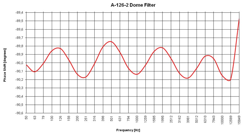
Das Dome-Filter des A-126-2 liefert eine Phasenverschiebung von 90 Grad mit weniger als 0,3 Grad Abweichung im Frequenzbereich von ca. 50Hz bis 14kHz.
-
Einen in der Frequenz einstellbaren Sinus/Cosinus-Oszillator (sog. Quadratur-Oszillator) ähnlich zu den bereits existierenden Module A-143-9 oder A-110-4
-
zwei Multiplizierer: hier kommen im A-126-2 zwei Ringmodulatoren zum Einsatz, bei optimaler Justierung liegt das Übersprechen des Quadratur-VCOs ohne Squelch-Funktion bei ca. -54dB (entsprechend ca. 10mVss Störsignal zu 5Vss Nutzsignal). Das Übersprechen ist frequenzabhängig und ist bei höheren Frequenzen stärker als bei niedrigen.
-
eine Summiereinheit
-
einen Subtrahierer
Darüberhinaus verfügt das A-126-2 über einige Besonderheiten:
-
Aus dem Audio-Signal wird mit Hilfe eines sog. Hüllkurven-Folgers (engl. envelope follower) eine Steuerspannung erzeugt, deren Wert dem aktuellen Pegel des Audio-Signals entspricht. Mit Hilfe eines Komparators wird damit eine LED angesteuert, die als Übersteuerungsanzeige dient. Zusätzlich wird die Steuerspannung dazu verwendet, um einen VCA anzusteuern, der die sog. Squelch-Funktion übernimmt.
-
Die Up- und Down-Ausgänge sind intern mit einem spannungsgesteuerten Crossfader verbunden, so dass das Verhältnis zwischen Up- und Down-Signal stufenlos von Hand und mit Hilfe einer externen Steuerspannung eingestellt werden kann.
-
Alle Signalwege sind gleichspannungsgekoppelt, so dass auch sehr kleine Frequenzverschiebungen (mit einem externen Quadratur-VCO) möglich sind.
-
Wegen der Gleichspannungskopplung der Schaltung muss darauf geachtet werden, dass das eingehende Audio-Signal und ggf. die externen Sinus/Cosinus-Signale exakt nullsymmetrisch sind ! Andernfalls kommt es zu Artefakten auf Grund des Gleichspannungs-Offsets dieser Signale (z.B. deutliches Übersprechen/Durchschlagen des Sinus/Cosinus-Signals am Audio-Ausgang). Im Zweifelsfall sind Module mit Wechselspannungskopplung dazwischen zu schalten.
-
Das Modul ist komplett in konventioneller Durchsteck-Technik aufgebaut (auch das Dome-Filter), kein SMD.
-
Auf Grund des 100% analogen Aufbaus benötigt das Modul einige Minuten Aufwärmzeit bis alle Parameter stabil sind
-
Das Modul wird ab Werk für eine Spannungsversorgung von exakt +12,0V und -12,0V justiert. Falls die tatsächlichen Versorgungsspannungen von diesen Werten abweichen (z.B. 11,5V oder 12,5V) muss das Modul u.U. nachjustiert werden.
Das folgende Dokument erläutert
die Positionen der internen Stiftleisten (z.B. für die Verbindung zum
Expander-Modul A-126-2Exp), die Lage und Funktion der Trimmpotentiometer und die
Justiervorschriften: A126_2_internal.pdf.
In diesem Dokument ist auch die interne Verbindung zwischen Hauptmodul und
Erweiterungsmodul beschrieben. Die Verbindung erfolgt mit sog. Arduino-Kabeln.
Diese sind im Lieferumfang des Erweiterungsmoduls enthalten.
Das untenstehende Blockschaltbild zeigt den
inneren Aufbau des Moduls im Detail und die Phasenverschiebung des Dome-Filters
in Abhängigkeit von der Frequenz des Audio-Signals.
Sie finden untenstehend auch einige einfache Patch-Beispiele.
Hinweise zum Unterschied zwischen Version 1 und 2 von A-126-2
Der einzige Unterschied zwischen Version 1 und 2 des A-126-2 besteht
darin, dass Version 2 über eine zusätzliche interne Stiftleiste verfügt, die
bei Bedarf einen zweiten Audio-Eingang in Verbindung mit dem Expander-Modul zur
Verfügung stellt. Zum Zeitpunkt der Auslieferung von Version 1 des Moduls
(September 2021) stand jedoch noch nicht fest, ob ein Expander-Modul angeboten
wird oder nicht. Daher fehlt bei Version 1 dieser Eingang, da die Entscheidung
bezüglich des Expander-Moduls erst Ende 2021 getroffen wurde (also 3 Monate
nach der Auslieferung der Version 1 des Moduls). Es ist jedoch möglich, die
Version 1 zu modifizieren, so dass auch hier ein weiter Audio-Eingang zur
Verfügung steht. Näheres hierzu in dem Dokument
A126_2_internal.pdf.
Die Bedeutung dieser bei Version 2 hinzu gekommenen
Funktion sollte man aber nicht überschätzen. Es ist nichts
weiter als ein zweiter Audio- Eingang (ohne Abschwächer). Wir haben diesen zusätzlichen Eingang nur ergänzt, da
noch Platz für eine 8. Buchse am Expander-Modul war. Um ein Feedback aber sinnvoll zu integrieren wird zumindest ein
zusätzliches Abschwächer-Modul benötigt (z.B. A-183-1). Man kann das gleiche aber
auch mit einem kleinen externen Mixer (z.B. A-138n) erreichen. Diese Variante
bietet noch wesentlich mehr Möglichkeiten.
Weiter unten finden Sie hierzu zwei Patch-Beispiele:
das erste Beispiel zeigt die Realisierung der Feedback-Funktion, die für Version 1
und 2 des A-126-2 genutzt werden kann. Hier wird ein externer Mixer (A-138n) dazu
verwendet, um das eingehende Audio-Signal mit einem der Ausgänge des A-126-2 zu
mischen, um eine Rückkopplung zu erhalten. Da am A-138n weitere Eingänge zur Verfügung stehen, bietet diese Variante noch zusätzliche Möglichkeiten (z.B.
mehrfaches Feedback von verschiedenen A-126-2-Ausgängen oder als Mixer für 2
Audio-Signale für den Frequency Shifter).
Das zweite Beispiel zeigt die Realisierung der Feedback-Funktion, die für Version
2 des A-126-2 genutzt werden kann. Auch hier wird zumindest ein externes Modul (Abschwächer
A-183-1 oder Verstärker A-183-3) benötigt, um das Feedback in der Stärke einstellen zu
können. Die Preisdifferenz zwischen A-183-1 und A-138n ist jedoch so gering, dass wir auch bei der Version 2 des A-126-2 zu der Variante mit dem externen Mixer A-138n raten.
Die Versionen 1 und 2 kann man an Hand des Bestückungsdrucks oder der
verfügbaren Stiftleisten unterscheiden: bei Version 2 steht auf dem
Bestückungsdruck der unteren Leiterplatte "BOARD A VERSION 2"
in der Nähe des Buskabel-Anschlusses. Außerdem ist die Stiftleiste JP17 (AUDIO
IN 2) vorhanden, die bei Version 1 noch fehlt.
| click to enlarge | |
|
|
|
|
| main module | Expansion module |
|
|
| cable connections of the expansion module | |
Module A-126-2 is a fully analog frequency
shifter for audio signals.
A frequency shifter is an audio processing unit that shifts each frequency of
the incoming audio signal by the same frequency. If the shifting frequency is
e.g. 200Hz an incoming audio frequency of 1000 Hz becomes 1200 Hz, 2000Hz
becomes 2200 Hz, 3000 Hz becomes 3200 Hz and so on. Pay attention that this is
different from pitch shifting where all frequencies are shifted proportional (e.g. 1000>1200Hz, 2000>2400Hz, 3000>3600Hz) !
The frequency range of the internal quadrature VCO is about 8 octaves (about
20Hz ... 5kHz). If required an external quadrature VCO can be used.
The module is equipped with these controls, inputs and outputs:
-
Frequ. 1: first manual control of the shifting frequency (factory setting: coarse, range about 20Hz - 5 kHz)
-
Frequ. 2: second manual control of the shifting frequency (factory setting: fine)
-
by means of internal jumpers the sensitivity of Frequ.1 and 2 can be swapped (i.e. Frequ.1 = fine and Frequ.2 = coarse)
-
the relation between coarse and fine control is about 25:1 (corresponding to about 8 octaves to 1/3 octave)
-
FCV In (socket) and FCV (small control without knob): control voltage input with attenuator for the external voltage control of the shifting frequency
-
Mix: manual control of the up/down shift panning unit, fully CCW = down shift, fully CW = up shift, in between a mixture of down and up
-
Mix CV In (socket) and Mix CV (small control without knob): control voltage input with attenuator for the mixing unit for external voltage control of the up/down mixing
-
Audio In (socket), Level (small control without knob) and Overload (LED): audio input with attenuator, typ. audio in level = 1Vpp, the level control has to be adjusted so that the overload LED just begins to light up a bit, when the LED is fully on clipping/distortion occurs, when the LED is permanently off the input level is too low and the signal-to-noise ratio increases
-
Audio Out (socket): audio output of the frequency shifter
-
Squelch (small control without knob): controls the squelch function: fully CCW (Env.) the output VCA is controlled by the envelope signal, which is derived from the audio input signal, fully CW (open) the output VCA is permanently open (no squelch function), in between the squelch intensity can be adjusted
-
Quadrature VCO Outputs (sockets Sin and Cos): outputs of the internal quadrature oscillator, about 12Vpp level (+6V/-6V)
-
Ext. Inputs Sin and Cos (sockets): required when an external quadrature VCO (e.g. A-143-9 with a wider frequency range or A-110-4 with thru zero feature or A-110-6 with different waveforms) is used instead of the internal quadrature VCO, the levels of the external VCO should be about 10Vpp (8...10Vpp are OK) and the signals have to be symmetrical around zero Volts, the sockets are normalled to the internal quadrature VCO (i.e. the sockets are equipped with switching contacts that interrupt the internal connection as soon as a plug inserted)
-
VCA ext. CV (socket): used when an external control voltage (e.g. from an envelope generator) should be used to control the output VCA instead of the internal squelch unit, the socket is normalled to the output of the squelch control (i.e. the socket is equipped with a switching contact that interrupts the internal squelch connection as soon as a plug inserted). From about +8V external control voltage the VCA is fully open.
-
Internal terminals (single pin headers for the connection to the expansion module A-126-2Exp or own DIY applications):
-
envelope follower output
-
dome filter output 1
-
dome filter output 2
-
ring modulator 1 output
-
ring modulator 2 output
-
Up shift output
-
Down shift output
-
Audio Input #2 for feedback effects (available only from version 2 of the module early in 2022)
-
GND
-
Technical details:
The analog frequency shifter is based on these trigonometric equivalences:
-
sin(a)*sin(b) = cos(a-b) - cos(a+b)
-
cos(a)*cos(b) = cos(a-b) + cos(a+b)
Building the sum and difference of these formulas one obtains:
-
Sum: sin(a)*sin(b) + cos(a)*cos(b) = 2 cos(a-b)
-
Difference: sin(a)*sin(b) - cos(a)*cos(b) = -2 cos(a+b)
When (a) in these formulas is treated as an audio signal and (b) as a sine signal it's possible to derive an up or down frequency shift with the frequency amount (b) for the audio signal (a). To realize the formulas these electronic circuits are required:
-
A phase shifter that shifts all frequencies of the audio signal (a) by 90 degrees (sine and cosine are the same signals but with 90 degrees phase difference). Such a circuit can be realized by means of a so-called Dome filter (named after the inventor Robert Dome). The circuit is made in principle with several allpass filters which have to be dimensioned very carefully so that the phase shift for all relevant frequencies is as close as possible to 90 degrees. In the A-126-2 a 12-stage Dome filter is used which is made with close-tolerance parts (resistors with 0.1% tolerance and capacitors with 1% tolerance). That way the time killing adjustment of many trimming potentiometers (with mutual influence) is avoided.
-
The Dome filter of the A-126-2 generates 90 degrees phase shift with less than 0.3 degrees error over a frequency range of about 50 Hz to 14 kHz.
-
A quadrature oscillator (i.e. an oscillator with simultaneous sine and cosine output, similar to the already existing modules A-143-9 or A-110-4
-
two multipliers: in the A-126-2 two ring modulators are used for this job, with optimal adjustment the feedthrough of the quadrature VCO is about -54dB (according to typically 10mVpp feedthrough compared to 5Vpp max. signal level) without squelch function. The feedthrough amount depends upon the shifting frequency and increases with the frequency.
-
a summing unit
-
a subtracting unit
Beyond that the A-126-2 has some special features:
-
An envelope follower is used to derive an envelope signal from the audio signal. It generates a voltage that corresponds to the current level of the audio signal. A comparator is used to drive an LED which works as overload display. In addition the envelope signal is used to control a VCA which works as a squelch unit.
-
The up and down outputs are internally connected to the inputs of a voltage controlled crossfader. That way the relation between up and down signal can be controlled manually and by means of an external control voltage.
-
The module is fully DC coupled so that even very low frequency shifts are possible (with external quadrature VCO)
-
Because of the DC coupling one has to pay attention that the incoming audio signal and possibly external sine/cosine signals are exactly zero-symmetrical. Otherwise artefacts will occur (e.g. loud feedthough of the sine/cosine signals at the output because of a DC offset of the incoming audio signal). In case of doubt AC coupled modules should be inserted in the signal paths.
-
The module is complete built in thru-hole technique (including the dome filter), no smt.
-
Because of the 100% analog circuitry the module requires a few minutes heat-up time until all parameters are stable
-
In the factory the module is adjusted for power supply voltages of exactly +12.0V und -12.0V. If the actual supply voltages differ from these values (e.g. 11.5V or 12.5V) the module may have to be readjusted.
The following document explains
the positions of the internal pin headers (e.g. for the connection to the
expander module A-126-2Exp), the positions and functions of the trimming
potentiometers and the adjustment procedures: A126_2_internal.pdf
This document explains also the connection between main module and the
expansion module. The connections are established by so-called Arduino cables.
They are included with the expansion module.
The sketch below shows the internal structure of
the module in detail and the phase shift of the dome filter.
Below you find also some patch examples.
Notes concerning the difference between version 1 and 2 of A-126-2
The only difference between version 1 and 2 of the A-126-2
is that version 2 is equipped with an additional internal pin header which
offers a second audio input in combination with the expander module. When the
delivery of version 1 started (September 2021) it was not yet sure if an
expander module will be available or not. That's why this additional output is
not availabe in version 1 because the decision for the expander module has been
made end of 2021 (i.e. 3 months after the delivery of version 1). But it's
possible to modify version 1 so that it also features a second audio input. For
details please refer to the document A126_2_internal.pdf.
The meaning of the additional audio input 2 is not that important as it
may seem at first sight. It has been just added because the expander module had an eighth unused
socket. The feedback feature is also possible with (unmodifed) version 1 of
the A-126-2. Below you find two patch examples in
this regard:
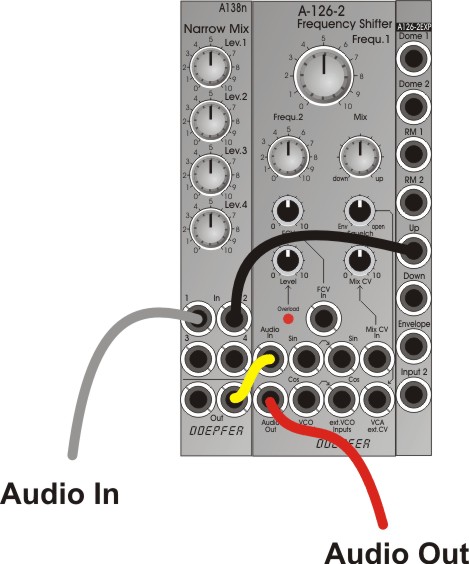
The first example shows a patch that can be used for both versions. It uses an
external mixer A-138n to realize the feedback function. The mixer is used to mix
the audio input signal with one of the outputs of the A-126-2. As the A-138n
still has two unused inputs these can be used e.g. for multiple feedback (i.e.
using two different outputs - e.g. Up and Down or Up and RM2 - simultaneously
for feedback, or as a mixer for two audio inputs for the frequency shifter).
The second example shows a feedback patch for version 2. To be able to adjust
the feedback amount at least an attenuator/amplifer (e.g. A-183-1,
A-183-2, A-183-3) is required. But this patch does not offer as many
possibilities as the version with the mixer A-138n. That's why we recommend the
first patch also for version 2 of the A-126-2. And the price difference between A-183-1 and A-138n is very
little.
Versions 1 and 2 can be distinguished by means of the PC board silk screen
printing or the available pin headers: the silk screen printing of the lower
board says "BOARD A VERSION 2" near the bus connector. And the
pin header JP17 (AUDIO IN 2) is available only for version 2.

(der zweite Audio-Eingang der Version 2 fehlt noch ist in diesem Schaltbild / the second audio input of version 2 is not yet shown in this schematics)
|
|
|
|
|
A-126-2 Feedback Example
1 The mixer A-138n is used to
add one of the output signals (e.g. Up, Down, RM1, RM2 or the Audio
Output) to the input signal. |
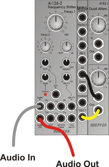
A-126-2 Feedback Example
2 The attenuator A-183-1 is
used to attenuate one of the output signals (e.g. Up, Down, RM1, RM2 or
the Audio Output) and add it to the input signal via the "Input
2" socket of the expander module. . |
|
|
|
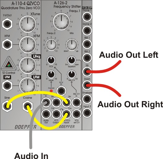
A-126-2 Stereo Example Instead of the Audio Output
of the main module the Up and Down outputs of the expander module are used
in this example as audio signals for left and right (even RM1/RM2 or Dome
1/2 may be used) |
Breite/Width: 8 TE / 8 HP / 40.3 mm
Tiefe/Depth: 60 mm (gemessen ab der Rückseite der Frontplatte / measured
from the rear side of the front panel)
Strombedarf/Current: +80mA (+12V) / -70mA
(-12V)
Standard Version : Euro 410.00
Vintage Edition : Euro 425.00
Breakout/Expansion Module:
Standard Version : Euro 55.00
Vintage Edition : Euro 60.00
The prices in US$ depend upon the exchange rate between Euro and US$ at the payment day.