A-157 Trigger Sequencer Subsystem
| Manuals: A157_1_Manual.pdf,
A157_2_3_Manual.pdf Anleitungen: A157_1_Bedienung.pdf, A157_2_3_Bedienung.pdf |
|||||
|
|||||
 |
|||||
|
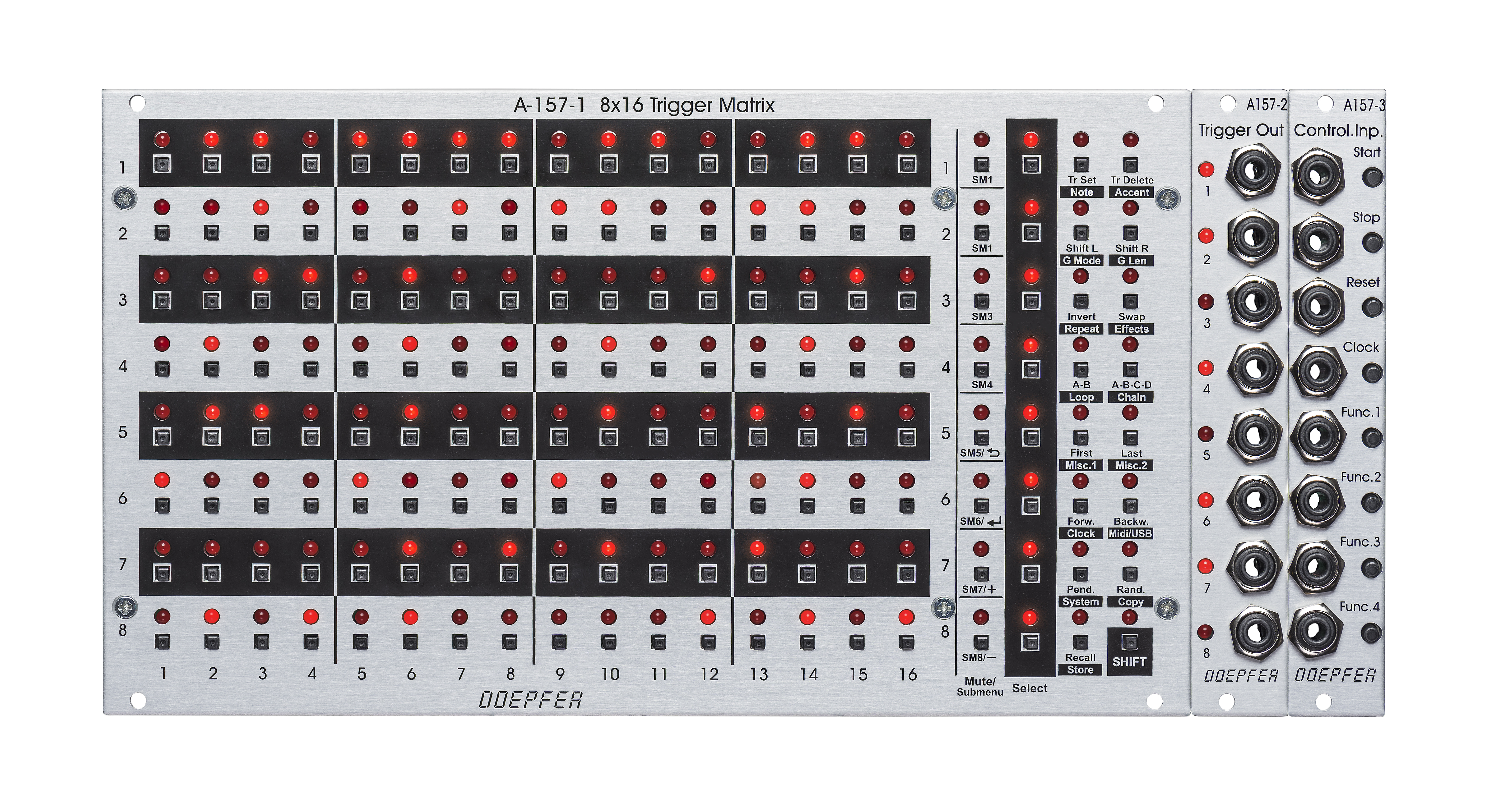
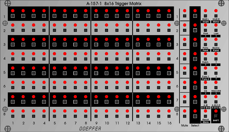
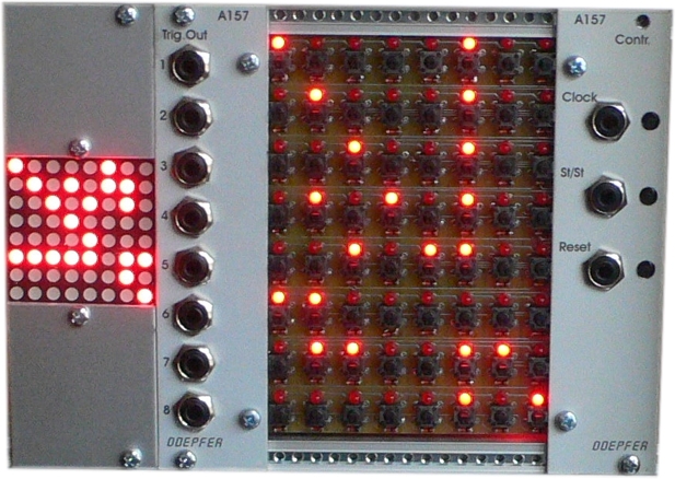
A-157 is a trigger sequencer subsystem that generates
eight trigger signals controlled by a 8x16 LED/button
matrix (some customers call it "Miniature Schaltwerk" as it is based
on the same matrix as the no longer available Schaltwerk).
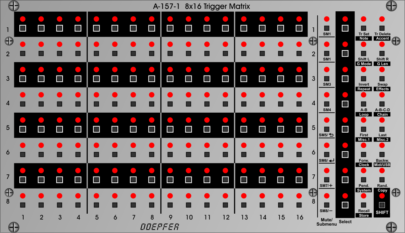
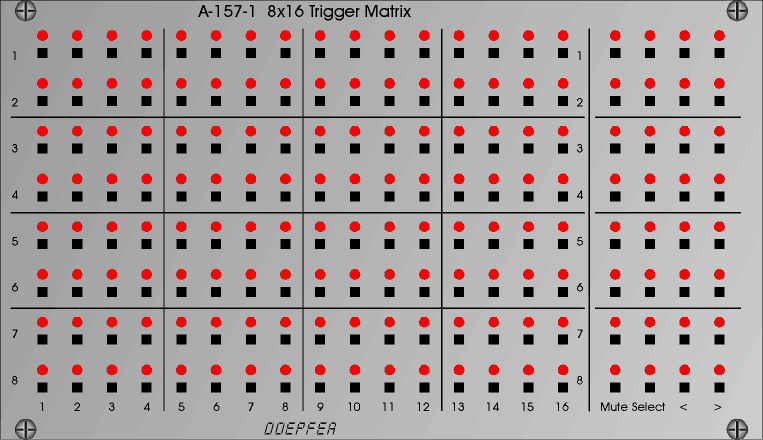
The LED/button matrix module A-157-1 is the core
of the subsystem. It is used to set or reset the trigger event on each of the 16
steps of each of the 8 rows. In addition the buttons and LEDs of the matrix are
used for other functions too (like setting the first and last step
of each row or adressing the preset memory). A-157-1 In addition to the main 8x16 matrix this modules contains also the buttons and LEDs for these functions:
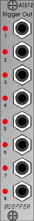
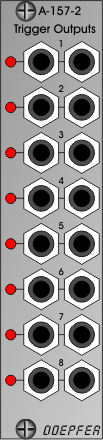
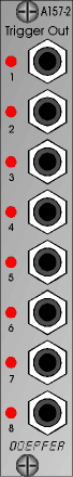
A-157-2 This
is the trigger/gate output module that has 8 sockets with assigned
LEDs available. The width of the output signal depends upon the
width of the incoming clock signal, i.e. the width of the output
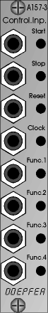
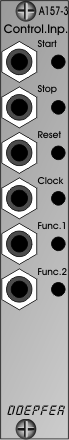
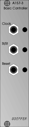
signals is the same as the width of the incoming clock signal. A-157-3 This module is the master control unit for Start, Stop, Reset and Clock. In addition four function controls and inputs are available that will be used in future firmware versions to address certain functions also from external signals (e.g. shifting a row ). Each function has a manual operated button and a control input. The voltage at each input has to be +3V... +12V to trigger the function in question. Important
technical note for A-157-3: The pin header
JP2 at the bottom edge of the pcb is unused so far. It is labelled
"(OPTION) START/STOP/RESET BREAKOUT" and is planned for a
Start/Stop/Reset/Clock breakout module. That's why the A-157-3 module is
delivered without a cable connected to JP2 ! The three modules are internally connected via ribbon cables and can be arranged also in another layout (e.g. A-157-2/3 on the right side of the A-157-1 or in a row above or below). The modules are available only as a complete set. If some of the further
features ( f.e. AB,ABCD-Mode and Reload/Save did not work, as described in the Attention with Reset: Operating the reset button/input
signal prepares the sequencer to jump to the first step as soon as the next clock signal (!)
appears. We believe that it makes more sense to carry out the jump to the first step not until the
next positive clock transition occurs. Otherwise the next clock would cause an advance to step 2 (in forward
mode and first step =1). Especially for synchronous operation of several sequencers this type of reset control
is more useful from our point of view. |
|||||
|
|
|||||
| Breite/Width: A-157-1: 44 TE/HP (223.2 mm) /
A-157-2: 4 TE/HP (20.0 mm) / A-157-3 mm: 4 TE/ HP
( 20.0 mm) Tiefe/Depth: A-157-1: 40 mm, A-157-2: 35 mm, A-157-3: 45 mm (gemessen ab der Rückseite der Frontplatte / measured from the rear side of the front panel) Strombedarf/Current (A-157-1/2/3): +12V: 350 mA (all 128 LEDs of the matrix "on" and all mute and select LEDs "on" = worst case), 80 mA (all LEDs "off") -12V: 20 mA |
|||||
|
|
|||||
| Preis/Price: Euro 500.00 for the module combo A-157-1/2/3 (the
modules are available only as a complete set, not individually) The price in US$ depends upon the exchange rate between Euro and US$ at the payment day. |
|||||
|
|
|||||
| History of the A-157 development | |||||
 |
 |
 |
|||
|
Matrix Module
A-157-1 (44 HP = 223.2 mm) The above picture shows the final version of the A-157-1 front panel. We had to come to an end and to define the front panel printing. Unfortunately the front panel printing cannot be updated via USB like the firmware :-). We tried to include as many suggestions for additional features from customers as possible (e.g. Set and Delete of steps "on the run", Repeat = Ratcheting feature). |
Output Module A-157-2 (4 HP = 20 mm) final version November 2015 max. 12V trigger level, the level can be set via software |
l
Module A-157-3 (4 HP = 20 mm) final version November 2015, four function inputs, connection for optional outputs (breakout module) for Start, Stop, Reset and Clock |
|||
 |
|
|
|||
|
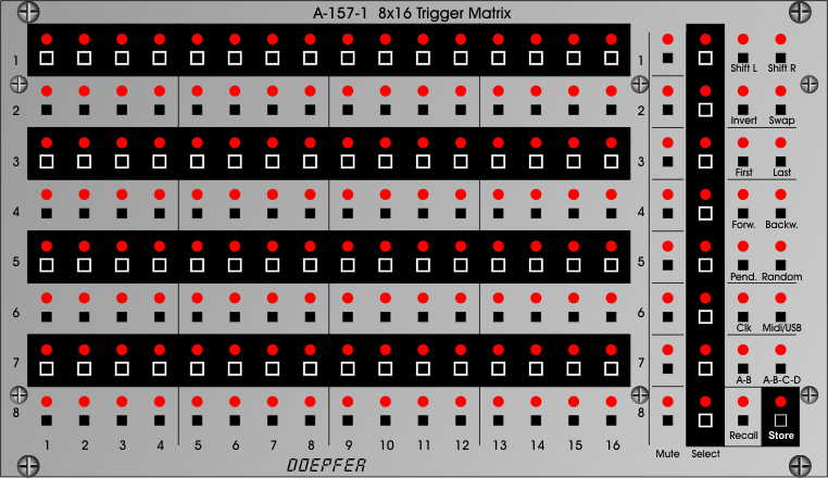
Matrix Module (revised version August 2015): It turned out that the control buttons at the right side of the module are not sufficient to include all the additional features customers are asking for. That's why we decided to add a SHIFT button at the bottom right side. Whenever SHIFT is activated (indicated by SHIFT LED = on) the lower function of each button is valid (black background / white printing). Otherwise the upper function (black printing) is valid. That way much more functions are possible and the pushing of two buttons at the same time can be avoided. The above picture shows just the basic structure. We are still about to define the final printing of the panel (it will be possible to update the firmware of the module via USB but not the front panel printing :-) As soon as the final functions are defined we will start with the front panel production and then also start the production of the module. It will be available about end of 2015 (as of November 2015). |
Output Module
(revised version September 2015):
only single output for each row |
Control
Module
(revised version September 2015):
2 more function inputs have been added |
|||
 |
 |
 |
|||
|
Matrix Module (revised version May 2015 based on customer suggestions at NAMM and Musikmesse):
|
Output Module |
Control Module | |||
 |
|
|
|||
| Matrix Module (version NAMM 2015, with modified function block for more features) |
Output Module (version NAMM 2015) |
Control
Module (version NAMM 2015) |
|||
 |
 |
 |
|||
| Matrix Module (new version summer 2014, with function block) | Trigger Output Module | Basic Control Module | |||
 |
|||||
| Matrix Module (old version, just 8x16 matrix without function block) | |||||
with an alternative display at the left side which will be not realized !
A-157 is a trigger sequencer subsystem that is used to generate up to eight trigger signals controlled by a 8x16 LED/button matrix (some customers call it "Miniature Schaltwerk" as it is based on the same matrix as the no longer available Schaltwerk). The system is still in the prototype state. Consequently the specifications on this page are still preliminary !
The subsystem will probably contain several modules:
- the LED/button matrix module A-157-1
- the trigger output module A-157-2
- one of the control modules (A-157-3, A-157-4 ...)
The LED/button matrix module A-157-1 is the core
of the subsystem. It is used to set or reset the trigger event on each of the 16
steps of each of the 8 rows.
The trigger output module A-157-2 outputs the 8 trigger signals and has an LED
display for each trigger. We will probably add a mute button or mute switch for
each row that allows to turn the trigger output off/on independent for each row.
In the final version the modules A-157-1 and A-157-2 will be probably merged
into one module only because both modules are essential for the subsystem.
The module A-157-1/2 (or the merged module that will contain both units) can be connected to a simple control module or a more sophisticated control module which is planned for the future (similar to the A-155 and A-154 conceptual design where the A-155 includes a simple control unit that can be replaced by the A-154 which offers a lot of additional functions).
At the beginning a simple control module A-157-3 similar to the A-155 control unit will be available. It offers only the functions clock, start/stop and reset (both with manual controls and control inputs). For this standard control unit the tempo (clock) is the same for all 8 rows, the direction is forward and the length of each row is 16.
We also plan a more complex control module A-157-4 that allows additional functions like 128 memories for trigger sequences, different clock/start/stop/reset for 2 or 4 groups of rows (e.g. common for rows 1-4 and 5-8, or in pairs), independent first/last step for each row, independent direction (forward/backward/pendulum/random) for each row, one-shot mode, LC display and so on. But these ideas are very preliminary and we will have to find out which functions are essential.
There are also plans for a stand-alone version adapted to the design of Dark Energy and Dark Time with the same case dimensions and wooden side panels (provisional name "Dark Flow")
Latest news (as of July 2014):
Based upon suggestions of customers the matrix board has been completely redesigned. The functions MUTE, SELECT, SHIFT LEFT, SHIFT RIGHT and INVERT ROW (when shift left and right are operated simultaneously) have been added for each row. This requires also a redesign of the processor board to support the new functions. Therefore the planned release date has to be postponed (without any obligation).
Latest news (as of May 2015):
Based upon suggestions of NAMM and Musikmesse visitors the matrix unit has been revised once again:
-
additional bright vertical separation lines in the black blocks
-
double functions for some buttons to obtain more buttons for additional features (e.g. Shift Left + Right = Swap, Forward + Backward = Pendulum)
-
two unused buttons (labelled "???") for new functions
-
some LEDs with different colors (e.g. steps 1/9 and Mute, just a suggestion, it's not for sure that different colors will be used and if applicable which colors will be used)
-
maybe we can add the ratcheting feature (but it's still unclear how to operate this feature with the existing buttons and LEDs
-
Two function inputs that can be assigned to any of the functions normally controlled by buttons (e.g. shift or invert), maybe they can be used also as additional clock signals (to have 2 or 3 different clocks available)