A-174-4 Joy Stick II

|
click to enlarge |
click to enlarge |
|

|
|
Standard Edition |
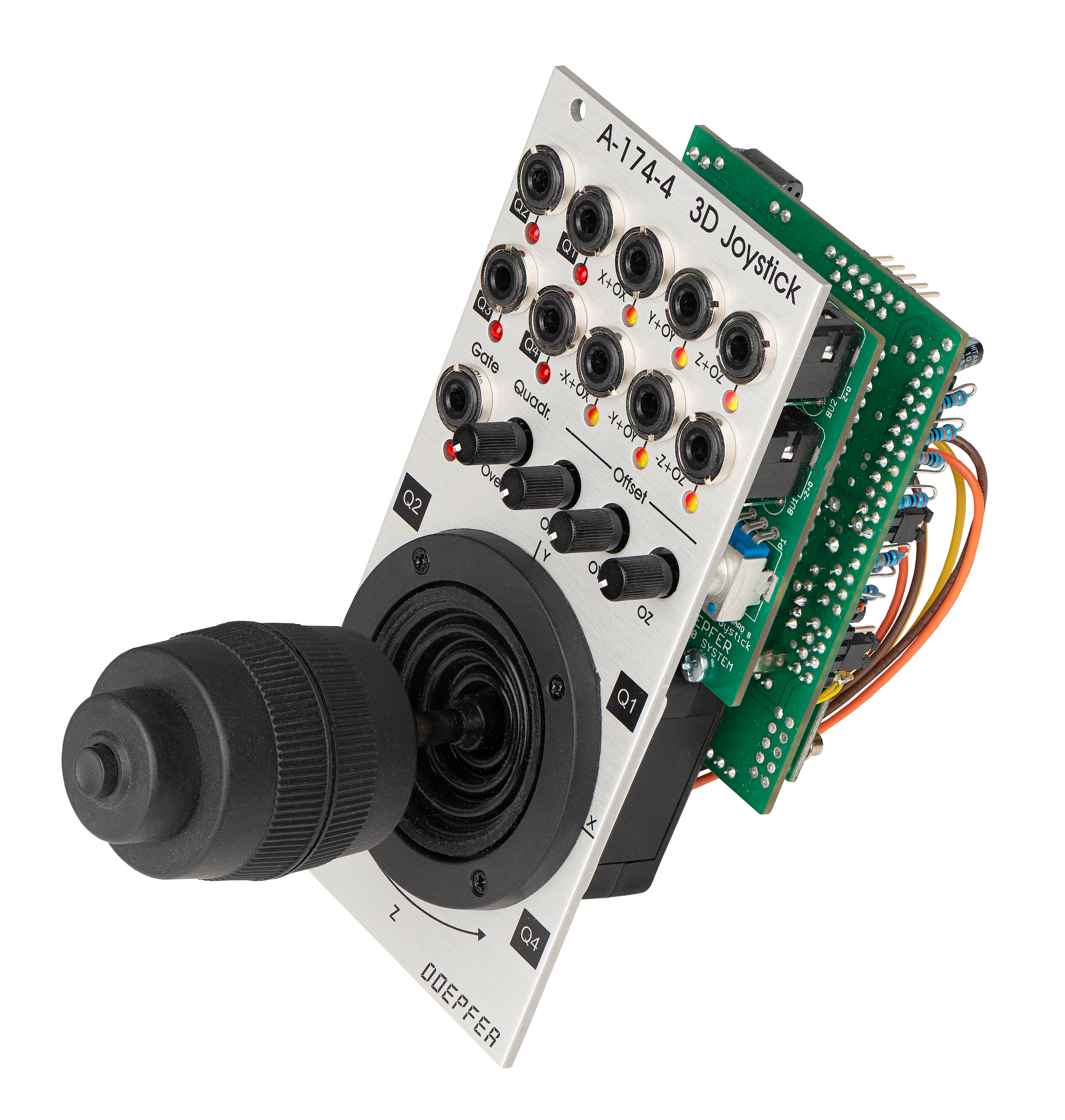
Vintage Edition |
|
|
|
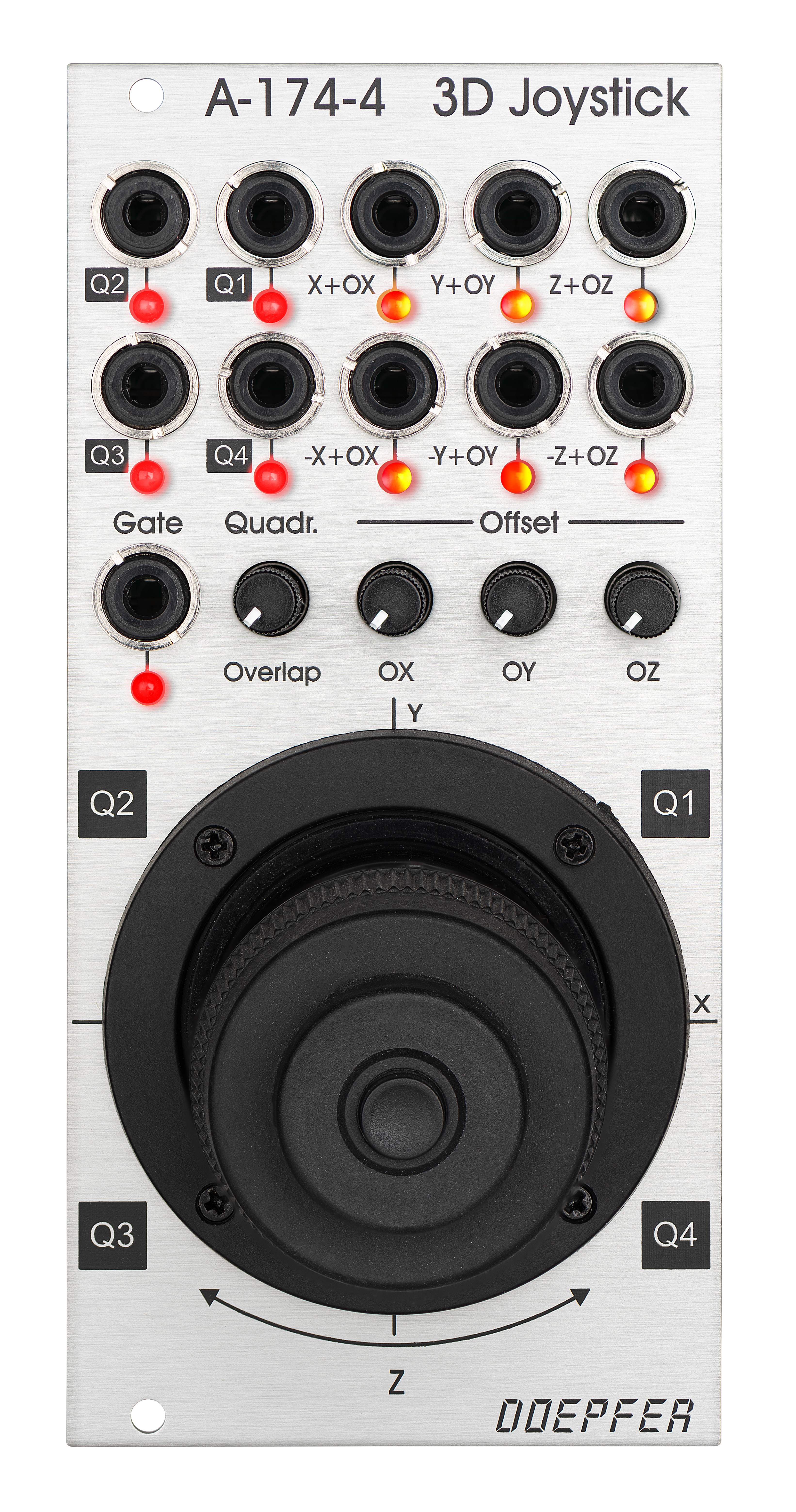
Das Modul A-174-4 erzeugt mehrere analoge Steuerspannungen und ein Gate-Signal mit Hilfe eines rückstellenden Kreuzpotentiometers (Joystick). Die Ausgangsspannungen X und Y werden in der üblichen Weise durch die X- und Y-Position des Joystick-Hebels definiert. Die dritte Steuerspannung (Z) wird aus der Drehung des Joystick-Bedienknopfs abgeleitet. Auch diese Funktion ist rückstellend. Mit Hilfe eines Tasters an der Oberseite des Joystick-Bedienknopfs kann ein Gate-Signal erzeugt werden. Als weiteres Feature werden vier zusätzliche Steuerspannungen erzeugt, die den vier Quadranten des kartesischen Koordinatensystems zugeordnet sind und aus den Werten von X und Y mit Hilfe eines speziellen Algorithmus abgeleitet werden.
Für jede Joystick-Funktion steht das nicht-invertierte Signal (X, Y, Z) und das invertierte Signal (-X, -Y, -Z) zur Verfügung. Die vom Joystick selbst erzeugten Spannungen liegen im Bereich -5V...+5V. Zu jedem Steuerspannungsausgang kann bei Bedarf eine Offset-Spannung (OX, OY, OZ) addiert werden, so dass beispielsweise die Steuerausgänge für X, Y und Z dann im rein positiven Bereich liegen (0...+10V statt -5V ... +5V). Das ist u.a. zur Steuerung von VCAs sinnvoll, da diese eine rein positive Steuerspannung benötigen. Zu diesem Zweck stehen drei Offset-Regler für X, Y und Z getrennt zur Verfügung. Steht der betreffende Regler auf Linksanschlag, so wird kein Offset addiert und es werden die "reinen" Spannungen X, -X, Y, -Y, Z und -Z ohne Offset ausgegeben (-5V...+5V für die nicht invertierten Ausgänge, +5V...-5V für die invertierten Ausgänge). Wird der betreffende Offset-Regler im Uhrzeigersinn gedreht, so werden je nach Reglerstellung bis zu +5V bei Rechtsanschlag zu der betreffenden Spannung addiert. Die Offset-Spannungen werden auch auf die invertierten Ausgänge addiert. So entsteht beispielsweise aus einem Spannungsbereich +5V...-5V bei maximalem Offset der neue Bereich +10V...0V. Diese Spannungen werden an den 6 Buchsen "X+OX", "-X+OX", "Y+OY", "-Y+OY", "Z+OZ" und "-Z+OZ" ausgegeben. Jeder Ausgang ist mit einer LED versehen, die die aktuell anliegende Spannung anzeigt. Diese LEDs sind zweifarbig (gelb/rot), um zwischen positiven (rot) und negativen (gelb) Spannungen unterscheiden zu können.
Zusätzlich werden vier Quadranten-Steuerspannungen Q1...Q4 erzeugt. Eine Quadranten-Steuerspannung ist nur dann positiv, wenn sich der Joystick-Hebel in dem betreffenden Quadraten befindet. Der absolute Spannungswert hängt dabei vom Drehwinkel bzw. der Position des Joystick-Hebels innerhalb des Quadranten ab. Mit Hilfe des "Overlap"-Reglers kann jedoch eine Überlappung zwischen den Quadranten-Ausgängen stufenlos eingestellt werden. Steht die Überlappung auf 0, so wird beispielsweise nur der Ausgang Q1 positiv, wenn sich der Hebel des Joysticks im ersten Quadranten befindet. Die anderen drei Quadranten-Spannungen sind dann Null. Erhöht man jedoch den Überlappungswert, so besitzen beispielsweise in der 12 Uhr-Stellung des Joysticks die beiden Ausgänge Q1 und Q2 einen positiven Wert, wobei dieser Wert von der Stellung des Overlap-Reglers abhängt. Je weiter der Regler aufgedreht wird, um so weitergehend ist die Überlappung der an den Quadraten-Ausgängen anliegenden Spannungen. In einer Grafik werden wir diesen Sachverhalt in Kürze näher erläutern. Jeder Quadranten-Ausgang ist mit einer einfarbigen LED versehen, die die aktuell anliegende Spannung anzeigt. Die Quadranten-Ausgänge liefern nur positive Spannungen im Bereich 0...+10V.
Hinweise:
- Auf Grund der Bauhöhe des Joysticks von ca. 7 cm kann das Modul leider nicht in die Gehäuse A-100P6, A-100P9, A-100PMS6, A-100PMS9 und A-100PMS12 während des Transports eingesetzt werden, da die Deckel dieser Gehäuse nicht tief genug sind. In die Gehäuse-Unterbauten A-100PB und A-100PMB sowie alle anderen Gehäuse ohne Deckel kann das Modul jedoch problemlos eingebaut werden. Wir sind derzeit auf der Suche nach einer Lösung für das Problem (eventuell tiefere Deckel für die erwähnte Gehäuse, was aber auch eine Änderung bei den Verpackungskartons erfordert).
- Auf Grund der Ausladung des Hebels in den Extremstellungen (ganz nach links, rechts oder unten) kann es nötig sein, die benachbarten Module anders anzuordnen oder Blindplatten vorzusehen. Es hängt ganz von den Bedienelementen und Buchsen der benachbarten Module ab, ob das erforderlich ist.
- Es ist theoretisch möglich, die Rückstellfedern der X- und Y-Potentiometer zu entfernen. Hierzu muss muss das Gehäuse des Joysticks geöffnet und die Rückholfedern mit geeignetem Werkzeug entfernt werden. die Auf Grund der geringen Reibung kann aber dann nicht garantiert werden, dass der Hebel nach dem Loslassen in seiner letzten Stellung stehen bleibt. Wir raten daher von dieser Modifikation ab. Auch der Garantieanspruch geht verloren, wenn solche Modifikationen durchgeführt werden.
- Der Joystick ist ein Verschleißteil und unterliegt daher nicht der Gewährleistung.
- Bei diesem Modul befindet sich wegen der Lage des Joysticks der Anschluss für die Verbindung zum Bus an der Oberseite des Moduls (nicht an der Unterseite wie bei den meisten anderen Modulen).
Module A-174-4 generates several control voltages and a gate signal controlled by a spring-loaded X/Y cross potentiometer (so-called joy stick). The control voltages for X and Y are controlled by the X and Y position of the joystick in the usual way. The third control voltage Z is controlled by the rotation of the spring-loaded joystick knob. The gate signal is generated by a button at the center/top of the joystick knob. As an additional feature four control voltages are generated that are assigned to the quadrants of the Cartesian coordinate system. These quadrant voltages are derived from the X and Y voltages by means of a special algorithm.
For each joystick function the non-inverted signal (X, Y, Z) as well as the inverted signal (-X, -Y, -Z) is available. The generic joystick control voltages are bipolar and range from typ. -5V (lowest position) via 0V (center position) to typ. +5V (highest position). By means of the Offset controls OX, OY and OZ a variable voltage of up to 5V can be added to the generic voltages. That way it's possible that the X, Y and Z outputs become pure positive (0...+10V instead of -5V...+5V). That's necessary if e.g. VCAs have to be controlled, because VCAs require a pure positive control voltage. The offset voltages can be adjusted by means of three small potentiometers. When the control in question is fully CCW no offset is added and the "pure" control voltages X, -X, Y, -Y, Z and -Z without offset are generated. As soon as the offset control in question is moved clockwise up to +5V are added to the voltage in question. The offset voltages are also added to the inverting outputs. With max. offset the range of an inverted output becomes also pure positive (+10V...0V instead of +5V...-5V). These six voltages are output at the sockets "X+OX", "-X+OX", "Y+OY", "-Y+OY", "Z+OZ" and "-Z+OZ". Each of these outputs is equipped with a dual color LED (red/yellow) that displays the present voltage and allows to distinguish between positive (red) and negative (yellow) voltages.
On top of this the four quadrant voltages Q1, Q2, Q3 and Q4 are calculated. A quadrant voltage becomes positive when the joystick is positioned in the quadrant in question. The absolute value of the voltage depends upon the position of the joystick lever in the quadrant. By means of the Overlap control overlapping of the voltages between the quadrants is attainable. When the overlap control is fully CCW there is no overlapping, i.e. only the control voltage of the currently addressed quadrant becomes positive, all others are zero. As overlap is increased the voltages overlap more and more. E.g. both outputs Q1 and Q2 become positive in the 12 o'clock position of the lever when the overlap control is turned up. The overlapping increases with the position of the Overlap control. We will explain this behaviour by means of a drawing shortly. Each quadrant output is equipped with a single color LED that displays the present voltage. The quadrant outputs provide only positive voltages in the range 0...+10V.
Notes:
- Because of the construction height of the joystick (about 7 cm) the module cannot be installed into the cases A-100P6, A-100P9, A-100PMS6, A-100PMS9 and A-100PMS12 during transportation as the depth of the case cover is not sufficient. Into the base cases A-100PB and A-100PMB as well as in all other cases without cover the module can be installed without problems. We are about to find a solution for this problem (maybe deeper covers, but this requires also the modification of the cartons).
- Because of the outreach of the lever in the extreme positions (fully left, right or down) it may be necessaey to arrange the adjoining modules in a different way or to install blind panels instead of modules. It depends upon the controls and sockets of the adjoining modules if that's necessary.
- In theory it's possible to remove the return springs for the X and Y potentiometers. For this the joystick case has to be opened and the return springs removed by means of suitable tools. But because of the small friction it cannot be guaranteed that the lever will remain in the last position when it is released. That's why we do not recommend this modification. Even the warranty is void if such a modification is carried out by the customer.
- The joystick is a wear and tear part and is excluded from the warranty !
- For this module the bus connection is located at the top because of the position of the joystick at the bottom (in contrast to most other A-100 modules with the bus connection at the bottom)!
Breite/Width: 12 TE / 12 HP / 60.6 mm
Tiefe/Depth: 50 mm (gemessen
ab der Rückseite der Frontplatte / measured from the rear side of the front
panel)
Strombedarf/Current: +50mA (+12V) / -20mA
(-12V)
Standard Version : Euro 230.00
Vintage Edition : Euro 240.00
The price in US$ depends upon the exchange rate between Euro and US$ at the payment day.