![]()
|
|
|||||
| Insiders will know that there have been many suggestions and discussions since we announced the touch sensor keyboard more than three years ago. Unfortunately the discussions did not help us to focus on a final design as there were too many contradictions in the suggestions and we did not see the thread running through the story. In the meantime we have built three different prototypes of the touch sensor keyboard and two prototypes of the normal keyboard with moving keys. Now we started a new approch and hope it will satisfy all customers: as for many other projects we support now a modular concept, i.e. the keyboard and the additional functions (like sequencer) are separated units. Consequently the user is able to decide if he wants the touch sensor or the standard version of the keyboard and if he wants to have the additional features (like sequencer) available. In the following the new approach is presented (at the end of this page the former concept is still available but this is no longer valid). | |||||
| Overview A-100 Keyboards | |||||
|
The main idea is to separate
the keyboard from the control section and to offer a standard version
(with normal keys) as
well as a touch sensitive version of the keyboard. So the user can decide
if he prefers the touch sensor version or the normal keyboard.
The keyboards can be used as
simple monophonic CV/gate controllers even without the controller unit. In
addition the keyboards will be equipped with an output that tells the
controller option which keys are pressed at the moment. As we do not want
to introduce a new interface Midi will be used for this purpose.
Consequently the keyboards will be simple Midi keyboards too.
Two A-100 keyboards with CV and Gate outputs are planned:
Both keyboards can be used as stand alone devices with external 9V power supply and in/outputs at the keyboard or in combination with an A-100 frame. In this case a multicore cable is used to power the keyboard from the A-100 frame and the Gate, CV and Midi outputs are available at an A-100 front panel too. The Midi output is intended in the first place to drive the planned A-100 keyboard/sequencer controller but can be used to control other Midi equipment too (but the keyboards are not Midi keyboards in the first place). |
|||||
|
|
|||||
| Standard version of the A-100 keyboard | |||||
|
|
|||||
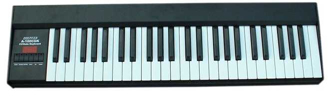
|
A-100CGK (with 4 octave keyboard and metal case) no longer available |
|||||
|
|||||
|
|
|||||
|
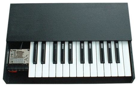
Prototype of the A-100CGK (OEM
version with a 3 octave keyboard) (the picture shows also the passive "interface board" that is planned to make the CV and Gate signals available at a normal A-100 front panel with 4 or 6 HP) no longer available |
|||||
|
The keyboard with standard keys A-100CGK is equipped with Gate, CV1 (pitch), CV2 (velocity), CV3 (after touch) and Midi outputs. The electronics inside the keyboard can be used in combination with 2, 3, 4 or 5 octave keyboards. But only the version with 4 octaves is available with a suitable metal case (see above picture). The other versions are available only as OEM products without housing. The housing has to be built by the customer (see above example with 2 octaves). Six buttons with assigned LEDs and a three digit display are used to adjust the keyboard parameters ( e.g. assign mode, retrigger mode, transpose, Midi channel). The Midi output is intended in the first place to drive the A-100 keyboard/sequencer controller that is in the planning stage, but can be used to control other Midi equipment too (but the keyboards are not Midi keyboards in the first place). |
|||||
|
|
|||||
|
An additional controller box that will be probably equipped with 2 wheels, a joy-stick, some buttons and switches is in the planning stage. The box will have probably the same depth and height as the keyboard case and can be mounted next to the keyboard. It will be probably equipped with several CV/gate outputs and can be used in combination with one of the keyboards or as a stand-alone unit to control analog equipment (several CV outputs controlled by the wheels and joy-stick, some gate outputs controlled by the buttons or switches). We also think about the possibility to add some inputs for foot switches and foot controllers. |
|||||
|
|
|||||
| Touch version of the keyboard with metal plates as touch sensors | |||||
|
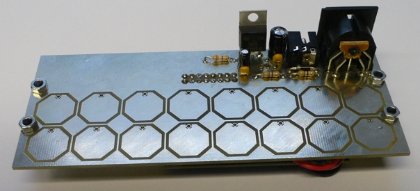
Third version of the Touch Sensor Keyboard NAMM 2010 |
|||||
|
The latest prototype shown at NAMM 2010 is equipped with 16 uniform metal plates and uses a new working principle (no longer the hum noise of the fingers but the capacity change of the pads). We will start a poll after the NAMM 2010 to decide if the TKB will be manufactured at all and which version (if applicable). The number, shape and dimensions of the pads can be adjusted to the customers wishes but we will be able to manufacture only one or maybe two versions (e.g. one with a keyboard layout like version 1 and 2 and another with a non-keyboard layout like version 3). In any case it is planned to separate the control until (i.e. the potentiometers, sockets, LEDs and so on) from the touch section. The touch section could be like a module (i.e. assembled like a module to the frame) or a separate box with a cable that leads to the control module (or external control box for stand-alone applications). |
|||||
|
|
|||||
|
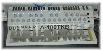
Second Prototype of the Touch Sensor Keyboard NAMM 2007 / Musikmesse Frankfurt 2007 |
|||||
|
The touch version of the keyboard will be equipped with probably 25 metal plates (2 octaves) that respond to the touch of a finger (no moving parts). For the first two versions of the TKB the hum noise inducted by the sourrounding mains was used as working principle. But we found that this principle does not work perfect in all cases (changing mains intensity, different mains frequencies 50/60Hz, indoor/outdoor, problems with increasing humidity and some problems more). This is why we are about to try another approach with capacitive sensing. At present we cannot prognose a release date or price for the TKB. If we are satisfied with the results the TKB may go into production about end of 2010 (without any obligation). As an option we think about a pressure sensor below the keys that measures the pressure applied to the metal plates. The touch keyboard will be probably equipped with outputs for Gate, CV1 (pitch), CV2 (pressure) and Midi. Due to the nature of the keyboard velocity measurement is not possible and even the Midi output is monophonic only. Suitable supports to mount the keyboard case into a 19" rack at different positions and angles are planned for the touch version of the keyboard (not possible for the normal version as the width is more than 19"). We also think about a DIY version of the TKB, i.e. only an electronics without the metal plates that can be used to connect any metal plates that have to be added by the user. |
|||||
|
|
|||||
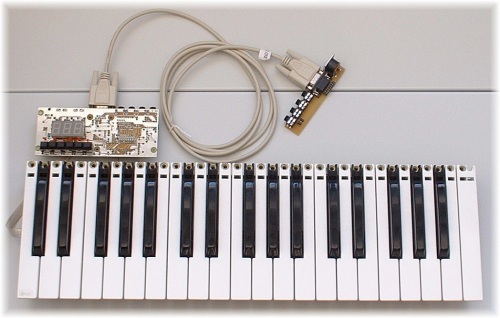
| Sequencer Controller | |||||
|
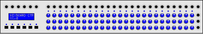
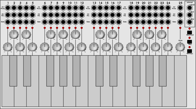
A separate controller section (probably a separate 19" case, not an A-100 module) will offer the additional functions that were included in the keyboard in the former concept. This is a first draft of the controller section (only for discussion, controls shown are only an example): |
|||||
|
|
|||||
|
The controller receives it's
information from the keyboard (touch or normal version) and generates the
corresponding functions similar to the former
concept. We think about several rows with 25 potentiometers each (three in the
picture, with a common row of LEDs) that can be used for different
functions. Above the potentiometers and LEDs the 25 single gate outputs
will be available. The number of 25 is chosen as this corresponds to the
planned number of keys of the touch keyboard or the 2 octaves version of
the normal keyboard.
The distance between the potentiometers is the same as for the keys of the
keyboards (~ 14.1mm). A smaller version of knobs has to be used as the
A-100 standard knobs are too large for this distance. When the
keyboard is placed directly below the controller the potentiometers/LEDs/sockets
will align with the keys. The sockets right of the
potentiometer rows output the voltage of the corresponding row, i.e. the
voltage that corresponds to the position of the potentiometer addressed at
the moment. For each of these outputs can be (probably) chosen if it is
non-quantized or if any quantization is active (like A-156 or maybe even
with free programmable quatization table). The upper right socket will be
probably the common trigger output that outputs a trigger whenever another
gate (i.e. one of the 25 single gate outputs) becomes active. All other
in/outputs (probably four CV and four gate outputs, clock/start/stop
inputs) will be located at the left side above the blue/white LCD. In the
picture above only 6 of these sockets are shown. The buttons and LEDs
below the LEDs are used to select the desired mode and to program the
entire device. Maybe a rotary encoder will be added too.
Even more than one controller can be connected to the same (or another) keyboard to
have more functions available (e.g. more sequencer rows). Here are some ideas how the controller could
work:
Monophonic mode Polyphonic mode Design idea: monophonic and polyphonic mode are available simultaneously and distinguished by the Midi channel only. E.g. if the controlling keyboards transmits data on channel 1 they are used for the monophonic mode as described above. CV#1, Gate#1 and CV#2 output monophonic pitch CV, Gate and velocity CV. The column is addressed by the key. Channel 2 is used for polyphonic mode. CV#1...4 and Gate#1...4 output polyphonic CV/Gate (no velocity CV). Maybe a duophonic mode with velocity CV is available too. We don't think that a 4 voice polyphonic mode with velocity CV is necessary (4 additional CVs required, each CV needs an expensive digital/analog converter). Consequently a small switch on the keyboard (channel 1/2) decides how the keyboard data are processed in the controller. Analog sequencer mode Digital sequencer mode These are the first ideas only and maybe some suggestions will be added or cancelled. |
|||||
|
|
|||||
|
Former
version of the A-100 Touch Keyboard |
|||||
|
|
|||||
|
|
|||||
|
|
|||||
Hier das
wichtigste in Stichworten
Anmerkung: Diese Information ist nicht als verbindliche Produktankündigung zu verstehen. Es ist nicht sicher, ob und in welcher endgültigen Form dieser Artikel in Produktion gehen wird. Wir stellen auf der Musikmesse im März 2002 den Prototypen vor und werden die Produktionsentscheidung vom Kundeninteresse abhängig machen. Der genaue Erscheinungstermin, die endgültiges Eigenschaften und der endgültige Preis stehen noch nicht fest, da auch die endgültigen, von unseren Kunden gewünschten Eigenschaften den Preis beeinflussen werden! Wir werden im Dialog mit interessierten Kunden in den nächsten Monaten die endgültigen Eigenschaften und den daraus resultierenden Preis endgültig festlegen. Einige der oben aufgeführten Eigenschaften beeinflussen den Preis sehr stark (z.B. separate Ausgänge für Gate, CVs für jede Taste, Drucksensoren unter jeder Taste, zusätzliche Potentiometerreihe) andere weniger stark (z.B. MIDI out, duophone CV/Gate-Ausgänge, zusätzliches 3-stelliges Display). |
An outline of the main points:
Remark: This information is not an obligatory product announcement. We do not guarantee that this device will go into production. At the Frankfurt music fair in March 2002 we will show the first prototype. The decision on the production will depend upon the customers inquiry. The delivery date, features and price are not yet fixed. The delivery date and price will depend upon the customers wishes. Some of the features mentioned above will have a significant influence on the price (e.g. pressure sensors, separate outputs for CVs and Gate for each key, additional row of potentiometers) others not that much (e.g. MIDI out, duophonic CV/Gate outputs, additonal display). After consultation with interested customers and observation of newsgroup discussions we will decide the final features and price during the next few months.
|
||||
| Breite/Width: ca. ? TE/about ? HP, Strombedarf/Current: ? mA | |||||
| Preis/Price: ca. Euro 300.00 - 400.00 (noch völlig unverbindlich, hängt von den endgültigen Eigenschaften ab) about Euro 300.00 - 400.00 (still completely uncertain, depends upon the final features), i.e. about US$ 300.00 - 400.00 lieferbar ca. ? (Preis, Termin und Eigenschaften sind noch völlig unverbindlich) available about ? (price, date and features are still without obligation) |
|||||