A-118-2 Noise /
Random / T&H / S&H
Slim Line Series
| click to enlarge | click to enlarge |
 |
|
|
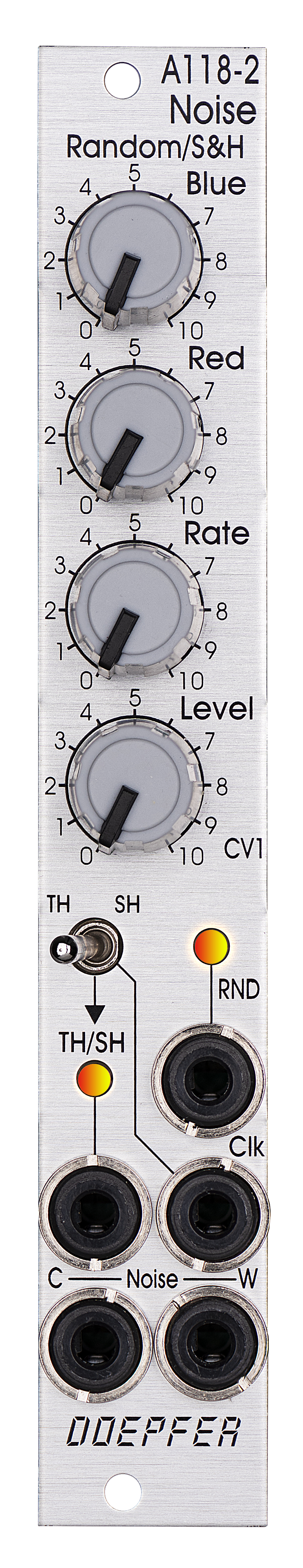
Standard Edition |
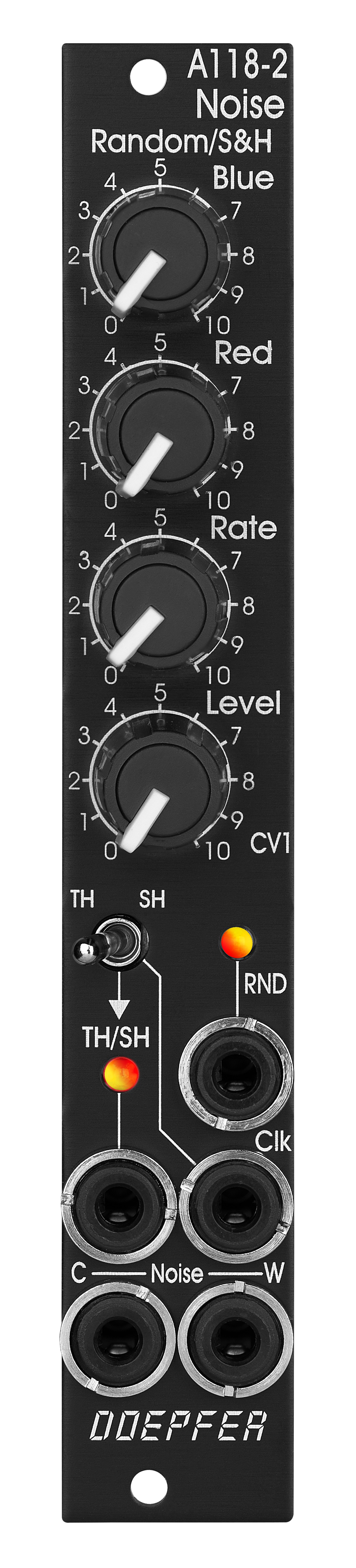
Vintage Edition |
Das Modul A-118-2 ist die schmale Version des Moduls A-118-1 und verfügt im wesentlichen über die gleichen Funktionen wie A-118-1. Die Bedienelemente sind jedoch enger angeordnet und es kommen kleinere, gummierte Drehnöpfe zum Einsatz. Dafür ist die Frontplatte mit 4TE nur halb so breit wie die des Moduls A-118-1. Es ist daher in erster Linie für Anwendungen gedacht, bei denen wenig Platz zur Verfügung steht. Der funktionelle Unterschied zum A-118-1 besteht darin, dass zusätzlich eine T&H/S&H-Einheit vorhanden ist.
Das Modul generiert die Signale weißes Rauschen (engl. white noise), farbiges Rauschen (engl.
colored noise), eine kontinuierliche Zufallsspannung (engl. random voltage) und
eine stufige Zufallsspannung, die aus der kontinuierlichen Zufallsspannung mit
Hilfe der S&H/T&H-Einheit abgeleitet wird.
Das
Rauschsignal wird rein analog durch Verstärken des Rauschens eines Transistors
erzeugt. Weißes
und farbiges Rauschen werden als Audio-Signale verwendet, die Zufallsspannungen
als Steuerspannungen.
Beim farbigen Rauschen können der Rot-Anteil (tiefe Frequenzen) und Blau-Anteil (hohe Frequenzen)
getrennt geregelt werden, um die Klangfarbe des farbigen Rauschens individuell
einzustellen.
Bei der kontinuierlichen Zufallsspannung RND können Änderungsgeschwindigkeit
(Rate) und Amplitude (Level) eingestellt werden. Die Zufallsspannung wird aus
dem farbigen Rauschen mit Hilfe eines Tiefpasses abgeleitet und mit einer
zweifarbigen LED optisch angezeigt (rot = positive / gelb = negative
Ausgangsspannung).
Die kontinuierliche Zufallsspannung dient als Eingang für die
S&H/T&H-Einheit. Die Arbeitsweise kann mit Hilfe eines Kippschalters
zwischen S&H und T&H umgeschaltet werden. Bei Track&Hold folgt das
Ausgangssignal dem Eingangssignal solange der Clock-Eingang "high"
ist. Wechselt das Clocksignal auf "low", so wird die letzte
Analogspannung zwischengespeichert. Bei Sample&Hold wird das Eingangssignal
bei der positiven Flanke des Clock-Signal gespeichert. Die Ausgangsspannung der
S&H/T&H-Einheit wird ebenfalls mit einer zweifarbigen LED optisch
angezeigt. Für das Clocksignal wird eine "digitale" Steuerspannung
benötigt (z.B. Clock, Gate, Rechteckausgang eines LFOs). Mit langsam
veränderlichen CV-Signalen am Clock-Eingang funktioniert die
S&H/T&H-Einheit nicht !
Bedienelemente:
- Blue: Anteil der hohen Frequenzen am Ausgang für farbiges Rauschen (Colored Noise)
- Red: Anteil der tiefen Frequenzen am Ausgang für farbiges Rauschen (Colored Noise)
- Rate: Änderungsgeschwindigkeit der kontinuierlichen Zufallsspannung (Linksanschlag = schnell, Rechtsanschlag = langsam, arbeitet wir ein Slew-Limiter)
- Level: Amplitude kontinuierlichen Zufallsspannung
- TH/SH: Schalter zum Umschalten zwischen T&H und S&H
Ein/Ausgänge:
- RND: Ausgang der kontinuierlichen Zufallsspannung (mit LED-Anzeige)
- TH/SH: Ausgang der S&H/T&H-Einheit (mit LED-Anzeige)
- Clk: Clock/Trigger-Eingang der S&H/T&H-Einheit
- C Noise: Ausgang farbiges Rauschen
- W Noise: Ausgang weißes Rauschen
Technische Hinweise:
Es dauert nach der Inbetriebnahme einige Minuten bis die Rauschsignale und
die Zufallssignale ausgegeben werden. Das Modul ist nicht defekt, wenn kurz nach der
Inbetriebnahme keine Signale erscheinen !
Die S&H-, bzw. T&H-Funktion wird rein analog mit Hilfe eines
elektronischen Schalters gefolgt von einem Haltekondensator mit Pufferschaltung
realisiert. Die Spannung am Ausgang driftet in der Haltephase etwas, da sich der
Kondensator allmählich über parasitäre Widerstände entlädt. Die Drift hängt auch von Umgebungsfaktoren wie
z.B. der Luftfeuchtigkeit oder Temperatur ab.
Das Zufalls-Signal wird aus dem Colored-Noise-Signal durch Tiefpass-Filterung
abgeleitet. Daher ändern sich Art und Pegel des Zufallssignals
auch beim Verändern der Reglerstellungen
von Blue und Red. Bei bestimmten Kombinationen der
Reglerstellungen kann es zu Begrenzung ("Clipping") der
Zufallsspannung kommen (beispielsweise bei Reglerstellungen von Red und/oder Blue und/oder
Level im oberen Bereich). Falls das Zufalls-Signal oben oder unten begrenzt, müssen
Einstellungen der Regler von Red, Blue
oder Level reduziert werden.
Ähnliche Module:
Module A-118-2 is the slim version of module A-118-1 and offers essentially the same features as the A-118-1. But the distances between the controls are smaller and rubberized small-sized knobs are used. In return the front panel has 4 HP only which is half the width of the A-118-1. The module is primarily planned for applications where only limited space is available. The functional difference between A-118-1 and A-118-2 is the additional T&H/S&H unit which is not included in the A-118-1.
The module generates the signals white
noise, colored noise, continuous
random voltage and stepped random voltage
(derived from the continuous random voltage by means of a S&H/T&H unit).
The noise signal is generated 100% analog by
amplification of the noise of a transistor. White and colored noise are usually
used as audio sources. The random voltages are normally used as control voltages
(e.g. for filter frequency or any other voltage controlled parameter).
The A-118-2 gives you the ability to mix the relative amounts of Red (low frequency
component) and Blue noise (high frequency component) in the colored noise output.
For the continuous random voltage the rate of change (Rate) and amplitude
(Level) of the random voltage can be adjusted. The continuous random voltage is
derived from the colored noise signal by low pass filtering. Consequently the
settings of the controls for the colored noise (Blue, Red) affect the behaviour
of the random voltage ! A dual color LED (red = positive / yellow = negative
output voltage) indicates the continuous random voltage.
The continuous random voltage is used as source for the S&H/T&H unit.
The type of operation can be set to S&H (sample and hold) or T&H (track
and hold). When T&H is chosen the output signal follows the input signal (=
continuous random voltage) as long as the Clock input is "high". As
soon as the clock signal changes to "low" the last voltage is stored.
When S&H is chosen the input signal (= continuous random voltage) is sampled
at the rising edge of the Clock signal.
For the Clock signal a "digital" signal (e.g. Clock, Gate, rectangle
output of an LFO) is required. It does not work with slowly changing continuous
CV signals. Another dual color LED (red = positive / yellow = negative output
voltage) indicates the stepped random voltage.
Controls:
- Blue: share of the high frequencies in the the colored noise output
- Red: share of the low frequencies in the the colored noise output
- Rate: rate of change of the continuous random voltage (CCW = fast, CW = slow, works like a slew limiter)
- Level: amplitude of the continuous random voltage
- TH/SH: switches between T&H und S&H
Inputs and outputs:
- RND: continuous random voltage output (with LED display)
- TH/SH: stepped random voltage output (with LED display)
- Clk: Clock input of the S&H/T&H unit
- C Noise: colored noise output
- W Noise: white noise output
Important notes:
After power on it takes a few minutes until the two noise signals and the random
signals are generated. The module is not faulty when after power on the signals
do not appear immediately !
The
S&H/T&H function is realized by pure analog circuitry (electronic switch
followed by a holding capacitor and buffer). Consequently the output voltage
drifts a bit in the holding state because the capacitor is discharged by
parasitic resistors. The drift
depends also upon environmental conditions like humidity or temperature.
The random signal is derived from the colored noise signal by lowpass filtering.
Therefore the settings of the Blue and Red controls also change the kind and
level of the random voltage. With certain combinations of the
positions of the Red, Blue and Level controls clipping of the random voltage may occur (e.g.
high settings of the Red and/or
Blue and/or Level controls). When this happens the positions of Blue and/or Red and/or Level have to
be reduced.
Similar modules:
Tiefe/Depth: 40 mm (gemessen ab der Rückseite der Frontplatte / measured from the rear side of the front panel)
Strombedarf/Current: +20 mA (+12V) / -20mA (-12V)
Standard Version: Euro 100.00
Vintage Edition: Euro 110.00
The price in US$ depends upon the exchange rate between Euro and US$ at the payment day.