A-142-2 Dual Envelope Controlled VCA
|
click to enlarge |
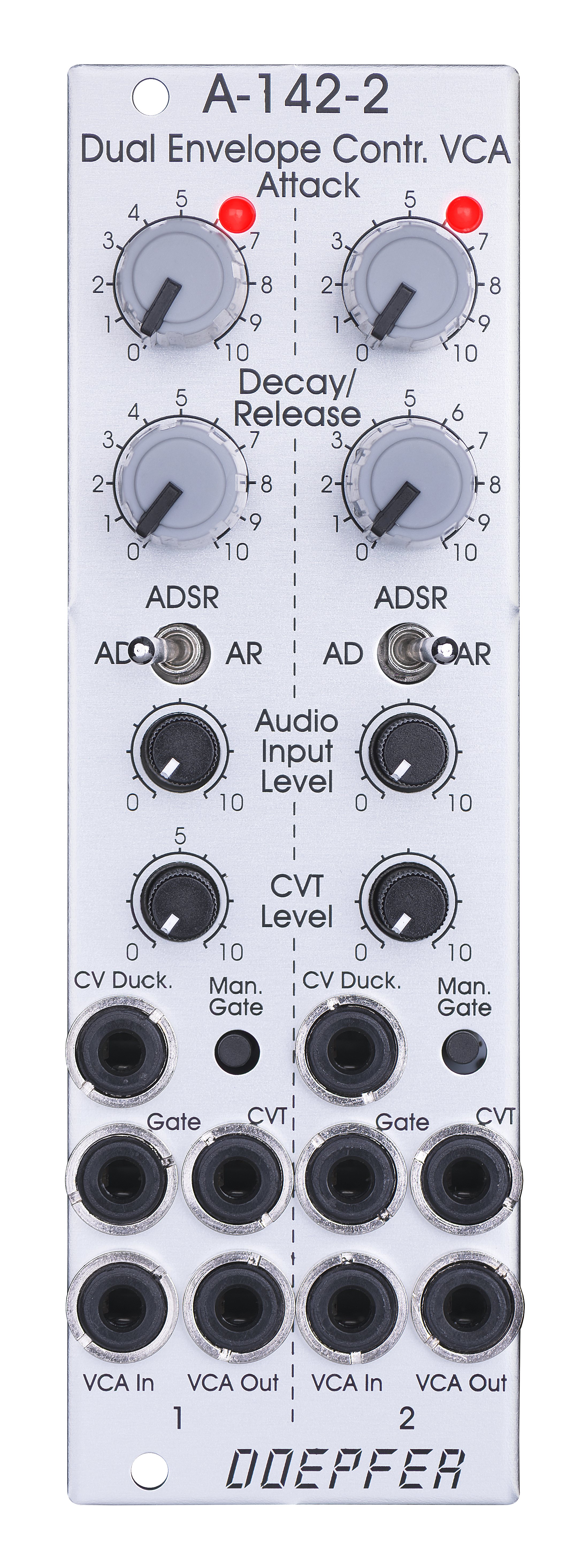 |
Die Hüllkurven-Generatoren besitzen exponentielle Kurvenformen (Lade/Entladekurven von Kondensatoren), die VCAs haben lineare Kennlinien.
Der Hüllkurven-Typ kann mit Hilfe eines Kippschalters gewählt werden:
- AD: Attack-Decay
- AR: Attack-Release
- ADSR: Attack-Decay-Sustain-Release mit der Einschränkung, dass Decay- und Release-Time gleich sind und der Sustain-Pegel fest vorgegeben ist (ab Werk = 50%)
Für jeden der beiden Einheiten stehen folgende Bedienelemente und Ein/Ausgänge zur Verfügung:
- LED-Anzeige (zeigt den Hüllkurven-Verlauf an)
- Attack: manuelle Einstellung der Attack-Zeit, ca. 500uS ... mehrere Minuten
- Decay/Release: manuelle Einstellung der Decay/Release-Zeiten, ca. 500uS ... mehrere Minuten
- Betriebsart-Schalter (AD, AR, ADSR)
- Audio Level: manuelle Einstellung des Audio-Pegels (Mini-Regler ohne Drehknopf)
- CVT: Abschwächer für CVT (Mini-Regler ohne Drehknopf)
- Gate-Eingang (min. +5V, max. +12V)
- manuelles Gate (Taster)
- CVT-Eingang (Zeitsteuer-Eingang)
- CV Duck.-Eingang (CV-Eingang für die Ducking-Funktion)
- Audio-Eingang
- Audio-Ausgang
Hüllkurven-AusgangDer Hüllkurven-Ausgang der ersten Version wurde zu Gunsten des Ducking-CV-Eingangs gestrichen. Intern ist auf der Leiterplatte jedoch eine 2-polige Stiftleiste verfügbar auf der das Hüllkurven-Signal (0...+10V) und der CV-Eingang des VCAs (0...+10V) für Modifikationen zur Verfügung stehen. Ab Werk sind die beiden Pins der Stiftleiste mit einer Steckbrücke verbunden.
Mit Hilfe von internen Steckbrücken (Jumpern)
kann für jede Einheit festgelegt werden, welche(r) der Parameter über den CVT-Eingang gesteuert
werden sollen (z.B. nur A oder nur D/R oder A und D/R) und in welcher
Richtung die Steuerung erfolgt, d.h. ob eine ansteigende Steuerspannung die Zeiten
erhöht oder verringert.
Mit Hilfe einer weiteren Steckbrücke wird festgelegt, ob das Gate-Signal der
Busplatine zum Ansteuern der betreffenden Hüllkurve verwendet werden soll
(getrennt für jeden Hüllkurven-Generator wählbar).
Und eine weitere Brücke legt fest, ob der Gate-Eingang 1 auf den Gate-Eingang
2 normalisiert wird (d.h. das Gate-Signal für Einheit 1 triggert auch die
Hüllkurve der Einheit 2).
Das folgende Dokument beschreibt
die Funktionen und Positionen der Steckbrücken (Jumper) des Moduls : A142_2_Jumpers.pdf
CV Duck ist ein zusätzlicher Steuereingang, mit dem der VCA mit Hilfe einer externen Steuerspannung stumm geschaltet werden kann. Ab ca. +5V wird dabei der Ausgang komplett stumm geschaltet. Im Spannungsbereich 0...+5V erfolgt nur eine partielle Stummschaltung. Schaltungstechnisch wird die Spannung am CV Duck-Eingang um den Faktor 2 verstärkt, invertiert und zu dem internen Hüllkurven-Signal (0...+10V) addiert. Das Summensignal dient dann zur Ansteuerung des VCAs.
Die Attack/Decay/Release-Zeiten liegen ca. zwischen 1ms und 30s (kann durch Ändern eines Kondensatorwertes auch in einen anderen Bereich verschoben werden).
Anwendung:
In nahezu jedem Patch sind
Kombinationen aus Hüllkurve und VCA in Verbindung mit einer Klangquelle
sinnvoll, insbesondere für perkussive Klänge.
Die Spannungssteuerbarkeit der Zeiten und des Duckings macht jede Performance
lebendiger.
Zusätzliche technische Informationen:
-
Der Spannungspegel des verwendeten Gate-Signals muss mindestens +5V betragen und steile Flanken aufweisen. Andernfalls wird die Hüllkurve nicht korrekt getriggert. Es hat sich gezeigt, dass einige Module anderer Hersteller diese Spezifikationen nicht erfüllen (Spannungswert zu niedrig oder Flankensteilheit zu gering). In diesem Fall kann das Zwischenschalten einer Einheit des Level-Shifter-Moduls A-183-4 das Problem beheben.
|
Module A-142-2 contains two envelope controlled VCAs
behind a front panel with 8 HP only. Each of the two sub-units is the combination of a
simple AD/ADSR/AR envelope generator and a VCA. The
envelope generators have exponential curve shapes (charge/discharge curves of a
capacitor). The VCAs have linear control scales.
The type of envelope can be selected by means of a toggle switch:
Each sub-unit provides these controls and in/outputs:
By means of two internal jumpers for each
sub-unit one can select which parameter(s) are controlled by the CVT input (e.g.
D/R only or A only or A and D/R) and in which direction (i.e. if an increasing CVT
shortens or stretches the time parameter in question). CV Duck is an additional control input for the VCA that can be used to mute the VCA by means of an external control voltage. Beyond about +5V CV Duck the VCA is fully muted, in the range 0...+5V there is only a partial muting. Circuitry-wise the CV Duck signal is amplified by two, inverted and added to the internal envelope signal (0...+10V). The sum of both signals is used to control the VCA. The time range of Attack/Decay/Release is about 1ms to 30s (can be modified by changing the value of a capacitor). Applications: Additional technical information:
|
Breite/Width: 8 TE / 8 HP / 40.3 mm
Tiefe/Depth: 45 mm (gemessen ab der Rückseite der Frontplatte / measured
from the rear side of the front panel)
Strombedarf/Current: +60 mA (+12V) / -60 mA
(-12V)
The price in US$ depends upon the exchange rate between Euro and US$ at the payment day.