A-160-5 Voltage Controlled Clock Multiplier / Ratcheting Controller
|
|
|
|
|
|
| Vintage Edition | |
Das Modul A-160-5 ist ein spannungsgesteuerter
Clock-Vervielfacher. Ein an der Buchse Clock In eintreffendes
Clock-Signal wird in der Frequenz vervielfacht. Der Multiplikationsfaktor hängt
von der an der Buchse CV In (0...+5V) anliegenden Steuerspannung und der
Stellung des Schalters Mode ab. Das in der Frequenz vervielfachte Signal
erscheint an der Buchse Clock Out. Je nach Stellung des Mode-Schalters
sind verschiedene Werte von Multiplikationsfaktoren den Steuerspannungswerten
zugeordnet. Bei 0V Steuerspannung wird kein Signal am Clock-Ausgang erzeugt. In
diesem Zustand leuchtet keine der acht LEDs auf, die den aktuellen
Multiplikationsfaktor anzeigen. Mit steigender Steuerspannung werden entweder
ganzzahlige Werte (linke Position des Mode-Schalters), 2er-Potenzen
(mittlere Position des Mode-Schalters) oder eine Mischung aus beiden
(rechte Position des Mode-Schalters) verwendet. Die acht LEDs unter dem
Schalter zeigen den aktuell eingestellten Multiplikationsfaktor an. Zwei weitere
LEDs zeigen das eingehende (Clock In) und ausgehende Signal (Clock Out)
an.
Mit dem Regler Manual kann der Multiplikationsfaktor von Hand eingestellt
werden (d.h. ohne eine extern zugeführte Steuerspannung). Der Regler erzeugt
eine Steuerspannung im Bereich 0...+5V, die auf die Buchse CV In
normalisiert ist (d.h. solange kein Patch-Kabel in die Buchse CV In
gesteckt wird, übernimmt der Regler die Einstellung des Multiplikationsfaktors.
Für eine dynamische Steuerung des Multiplikationsfaktors (z.B. für das
Erzeugen der unten beschriebenen Ratcheting-Funktion)
wird eine Steuerspannung der Buchse CV In von außen zugeführt. Diese
"überschreibt" dann die vom Regler kommende Steuerspannung. Der
Bereich der extern angelegten Steuerspannung muss im Bereich 0...+5V liegen.
Spannungen außerhalb dieses Bereichs haben keine Funktion, können aber das
Modul nicht zerstören.
Das Modul kann für jede Art von Clock-Frequenz-Vervielfachungen verwendet
werden. Ein wichtiges Beispiel ist die Erzeugung sog. Ratcheting-Sequenzen.
Die Gruppe Tangerine Dream ist bekannt für diese Art von Sequenzen. Ein normaler
Sequenzer erzeugt nur ein Gate- oder Trigger- Signal pro Stufe. Bei einer Ratcheting-Sequenz
werden für jede Stufe eine unterschiedliche Zahl von Gate/Trigger-Impulsen
erzeugt. Diese Funktion kann mit dem A-160-5 sehr einfach durchgeführt werden.
Hierzu wird eine Spur des Sequenzers dazu verwendet die Zahl der
Gate-Trigger-Impulse für jede Stufe einzeln zu definieren. Steht der Regler der
betreffenden Stufe auf Linksanschlag (0V CV), so wird kein Impuls erzeugt
(Mute-Funktion). Bei anderer Stellung des Reglers werden ein, zwei oder mehrere
Impulse für diese Stufe erzeugt.
Technischer Hinweis: Da das Modul nicht
"in die Zukunft" sehen kann, dauert es bei Änderung der
Clock-Frequenz an der Clock In-Buchse einige Impulse bis das Ausgangssignal an
der Clock Out-Buchse stabil ist. Das Modul ermittelt über einige Zyklen hinweg
die Frequenz am Clock-Eingang. Wenn sich diese Frequenz ändert, dauert es
einige Zyklen bis die für die Erzeugung des Clock-Ausgangssignals verwendete
Frequenz wieder korrekt ist. Daher sollte die Frequenz am Clock-Eingang
möglichst konstant sein oder sich nur langsam verändern. Das dürfte aber bei
den meisten Anwendungen der Fall sein.
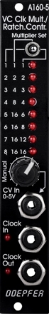
Der Schalter der ersten Produktionsserie war irrtümlich mit "Divider
Set" beschriftet. Ab der zweiten Serie ist der Schalter korrekt mit
"Multiplier Set" beschriftet.
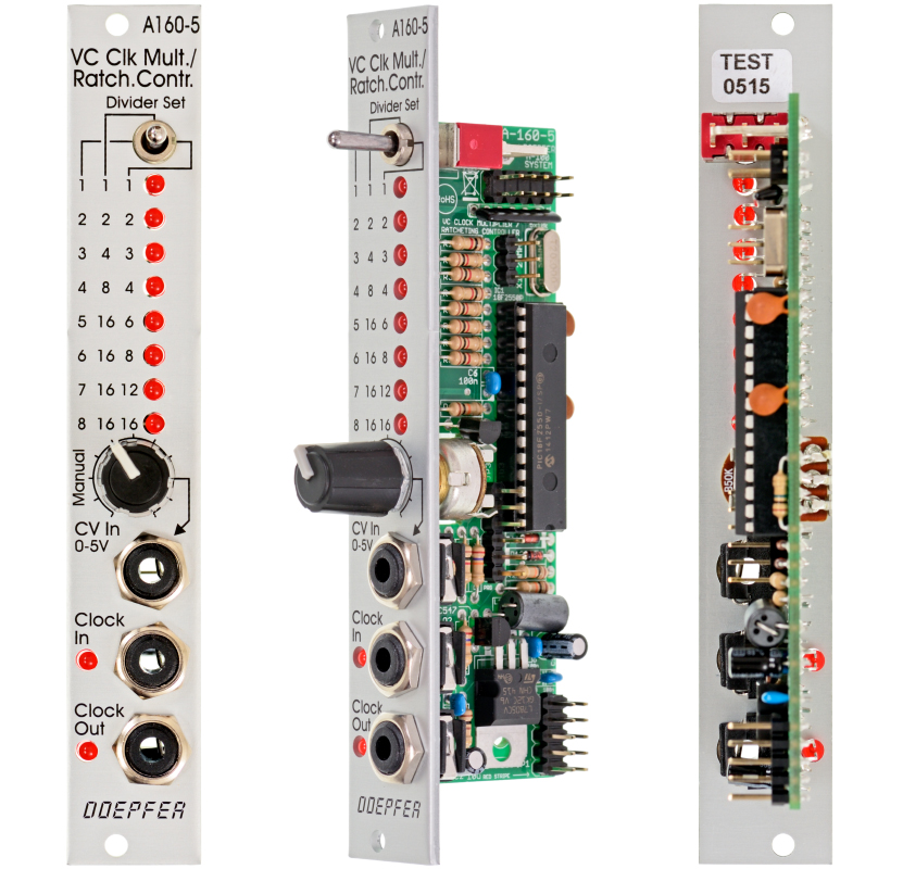
Module A-160-5 is a voltage controlled clock multiplier. The
incoming clock signal (socket Clock In) is multiplied by a factor that depends
upon the control voltage on socket CV In (0...+5V) and the position of the
Mode switch.
The multiplied clock signal is available at the socket Clock Out. According to the
position of the Mode switch different clock multiplying factors are assigned to
the control voltage. With 0V CV no clock output is generated. This state is indicated by "all LEDs off".
With increasing CV
integer factors (left position of the mode switch), power of two factors (middle
position) or a mix of both (right position) are obtained. Eight LEDs are used to
show the currently selected multiplying factor. In addition two LEDs are used to
display the incoming and outgoing clock signal.
A manual control is used to adjust the clock
multiplication factor manually without the need of an external control voltage. The
voltage generated by this control ("Manual") is normalled
to the CV In socket. As long as no plug is inserted into the CV In socket the
clock multiplication factor is adjusted by means of the manual control knob and
displayed by the LEDs. For dynamic applications (like the Ratcheting function
described below) the manually generated CV is overwritten by the external CV
which has to be fed into the CV In socket.
The module can be used for all kind of clock
multiplying applications. One important example is the generation of
so-called Ratcheting Sequences. The band Tangerine Dream is famous for
this kind of sequences. A normal sequencer generates only one gate signal per
step. A ratcheting sequence may have also more than one gate pulses per step.
This function can be obtained by using the A-160-5: one CV output of the
sequencer is used to define the number of gate pulses per step. If the control
of the step in question is fully CCW the generated CV is 0V and no gate signal
is generated (mute of the step). When the control of the step in question is
turned clockwise one, two or more gate pulses are generated depending upon the
position of the mode switch and the voltage generated by the CV at this step.
Technical note: Due to the nature of clock
multiplying it takes a few input clock pulses until the clock output is stable
when the frequency of the Clock In changes.
One has to average a few input clock pulses to generate the multiplied clock
output signal. Even when the input clock frequency changes it will take a few
cycles until the output clock signal is correct as the module cannot forsee the
future of the clock input signal. The generated clock output signal is derived
from the last few cycles of the clock input signal. Consequently the module
should be driven only by a clock signal with constant or slowly changing
frequency.
The switch of the first production series was labelled "Divider Set"
by mistake. From the second series the label has been corrected to
"Multiplier Set".
Patch-Beispiel zusammen mit dem Sequenzer A-155 / Patch Example with A-155 sequencer
Patch Example with A-154/A-155 sequencer combo
Breite/Width: 4 TE / 4 HP / 20.0 mm
Tiefe/Depth: 35 mm (gemessen ab der
Rückseite der Frontplatte / measured from the rear side of the front panel)
Strombedarf/Current: +50mA (+12V) / -0mA (-12V)
Preise
/ Prices:
Standard Version
: Euro 110.00
Vintage Edition : Euro 120.00
The price in US$
depends upon the exchange rate between Euro and US$ at the payment day.