|
click to enlarge |

Frontplatten-Ansicht des
zugehörigen Controller-Moduls |
|
Das Modul A-198-2 ist die verbesserte Version des
einfachen Trautonium/Ribbon-Controllers A-198-1.
Gegenüber dem A-198-1 bietet der A-198-2 eine Reihe von Verbesserungen:
- Gate-Erzeugung auch im Halte-Modus
- 9 vom Anwender programmierbare Quantisierungen,
dargestellt im Display als Tastatur mit einer Oktave (siehe untenstehende
Screenshots)
- Umschaltung quantisiert/nicht quantisiert am
Modul oder über den externen Steuereingang Qnt, der z.B. von einem
(Doppel-) Fußtaster gesteuert wird (A-177-2), um
während des Spiels dynamisch umzuschalten
- Umschaltung Retrigger an/aus am Modul oder
über den externen Steuereingang Rtr, der z.B. von einem (Doppel-)
Fußtaster gesteuert wird (A-177-2),
um während des Spiels dynamisch umzuschalten
- Spannungs/Ton-Umfang des Manuals (CV1) in
Oktavschritten von 1-5 einstellbar
- Bereich der ausgegebenen Druck-Spannung (CV2)
in mehreren Schritten einstellbar
- Ausrichtung des Manuals umschaltbar
- Offset-Spannungen für CV1 (Position) und CV2
(Druck) getrennt einstellbar
- Schwellenwert für Gate 2 (Druck) einstellbar
- Midi-Ausgang optional (statt der zweiten
Eingangs-Buchse Rtr oder über ein zusätzliches Breakout-Modul)
- Alle Parameter nicht flüchtig speicherbar (incl.
der 9 Quantisierungen)
- Bedienung mit Hilfe eines OLED-Displays und 9 rot beleuchteten Tastern
Als steuerndes Element wird der gleiche ca. 50 cm
lange Weg/Druck-Sensor wie beim A-198-1
eingesetzt.
Ausführliche Informationen zum Trautonium finden Sie auf unserer Homepage unter
diesem Link: Das
Trautonium-Projekt.
Funktionsbeschreibung des A-198-2
A-198-2 besteht aus 2 Einheiten:
dem Modul und dem Manual. Im Modul ist die Elektronik untergebracht, die die
vom Manual kommenden Daten (Fingerposition, Druck) in 2 Steuerspannungen
(CV1, CV2) und zwei Gate-Signale (Gate 1, Gate 2) umwandelt. CV1 und Gate 1
werden von der Position des Fingers auf dem Manual, CV2 und Gate 2 vom
ausgeübten Druck des Fingers gesteuert. Die CV- und Gate-Signale werden zur Steuerung anderer
Module verwendet. CV1 (Position) wird üblicherweise zur Tonhöhen-Steuerung
von einem oder mehreren VCOs verwendet. Gate 1 wird meist dazu benutzt einen
Hüllkurven-Generator zu triggern. CV2 (Druck) kann beispielsweise zur Steuerung
der Frequenz einer Filters oder der Lautstärke eines VCAs eingesetzt werden.
Mit Gate 2 kann ein weiteres Ereignis getriggert werden, sobald der auf das
Manual ausgeübte Druck einen bestimmten Wert übersteigt.
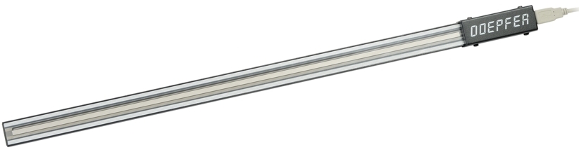
Das Manual besteht aus einem linearen Positionssensor und einem
Drucksensor. Die Sensoren sind in einem separaten, schwarz
beschichteten Metallrahmen
untergebracht.
Die Verbindung
zwischen Modul und Manual erfolgt über ein
4-poliges Kabel (wie für USB verwendet, an die Buchsen dürfen jedoch keine
USB-Geräte angeschlossen werden !).
Durch Berühren des Positionssensors mit dem Finger wird eine Steuerspannung CV1
erzeugt, deren Wert proportional zur Position des Fingers ist. Der Spannungsumfang von
CV1 bzw. die Skala von CV1 (d.h. welcher
Wegdifferenz welche Spannungsdifferenz entspricht) ist in Oktavstufen von
1 bis 5 einstellbar. Gleichzeitig wird ein Gate-Signal (Gate 1) erzeugt.
Üblicherweise steuert man mit CV1 einen oder mehrere Oszillatoren (VCO) an. Der
Gate-Ausgang 1 triggert üblicherweise einen Hüllkurven-Generator.
Bei der CV1-Ausgabe kann gewählt werden, ob diese stufenlos (wie beim
Trautonium) oder quantisiert (wie bei einem Keyboard) ausgegeben wird. Es stehen
9 vom Anwender frei programmierbare Quantisierungen zur Verfügung. Die
Quantisierungen werden im Display in der Art einer Tastatur dargestellt und
werden im Konfigurations-Modus mit Hilfe des Manuals sehr einfach programmiert.
Mit Hilfe des Positionssensors wird ein Cursor an die betreffende Stelle der
Tastatur bewegt. Über den Drucksensor wird die betreffende Quantisierungsstufe
dann an- oder abgeschaltet. Die gewünschte Quantisierung wird mit einem der 9
beleuchteten Taster angewählt. Durch nochmaligen Druck auf den betreffenden
Taster wird die Quantisierung abgeschaltet und im Display erscheint ein leeres
Keyboard. Stattdessen kann die Quantisierung
auch über den Eingang Qnt an/abgeschaltet werden. Mit Hilfe eines Fußtasters
ist eine dynamische Umschaltung während des Spiels möglich.
Im quantisierten Betrieb gibt es die Möglichkeit die Retrigger-Funktion an-
oder abzuschalten. Ist Retrigger angeschaltet so wird ein neues Gate-Signal
erzeugt (das Gate-Signal wird hierzu kurz unterbrochen), sobald eine neue
Quantisierungsstufe erreicht wird (auch wenn der Finger stufenlos auf dem Manual
verschoben wird). Ist Retrigger ausgeschaltet, so wird in diesem Fall kein neues
Gate-Signal erzeugt und der Finger muss abgehoben und erneut aufgesetzt werden,
um ein neues Gate-Signal zu erzeugen. Stattdessen kann die Retrigger-Funktion
auch über den Eingang Rtr an/abgeschaltet werden. Mit Hilfe eines Fußtasters
ist eine dynamische Umschaltung während des Spiels möglich.
Unter dem Wegsensor befindet sich ein empfindlicher Drucksensor, der eine weitere
Steuerspannung CV2 erzeugt, die mit höherem Druck ansteigt. Auch hier ist der
Spannungsumfang in mehreren Stufen einstellbar. Zusätzlich wird ein zweites
Gate-Signal wird beim Übersteigen eines bestimmten Drucks erzeugt. Der Schwellenwert, bei dem das Gate-Signal 2 erzeugt wird (Threshold), ist in mehreren
Stufen einstellbar.
Sowohl für CV1 wie auch CV2 kann eine Offset-Spannung programmiert werden, die
dem ausgegebenen Spannungswert fest addiert wird.
Die Daten des A-198-2 können auch über Midi ausgegeben werden (Position = Note
on/ff, Druck = Aftertouch). Hierfür muss
jedoch die Buchse Rtr geopfert werden. Durch Umstecken von internen Jumpern und
Kabeln kann die Buchse Rtr für Midi umkonfiguriert werden. Alternativ ist auch eine passives
Breakout-Modul denkbar (nur eine Midi-Buchse), das an die entsprechenden
Stiftleiste angeschlossen wird, die auf der Leiterplatte des A-198-2 dafür
vorgesehen ist.
Manual
Bedienungs- und Anzeige-Elemente:
-
schwarz/weißes
OLED-Display, zeigt die mit den Tastern gewählte Funktion und die
einstellbaren Parameter an (siehe unten abgebildete Screenshots)
-
Es
gibt zwei grundsätzliche Betriebsarten
-
Spielmodus
(Performance): das ist der Modus in dem gespielt wird
die
Beschriftungen über den Tastern gelten für den Spielmodus
-
Konfigurationsmodus
(Config): das ist der Modus in dem grundsätzliche
Parameter eingestellt werden,
die invers
dargestellten Beschriftungen unter den Tastern gelten für den Konfigurationsmodus
-
zwischen
den beiden Betriebsarten wird durch gleichzeitiges Drücken der Taster Quant.8
+ Quant.9 umgeschaltet.
-
9
Taster mit roter LED-Anzeige:
-
Quant.1 / Sensor:
Anwahl von Quantisierung 1 / Wahl des Sensors (Position oder Druck)
-
Quant.2 / Range:
Anwahl von Quantisierung 2 / Einstellung des Spannungsbereichs (Range)
des zuvor gewählten Sensors
-
Quant.3 /
Direction:
Anwahl von Quantisierung 3 / Richtung des zuvor gewählten Sensors (up/down)
-
Quant.4 /
Quantize:
Anwahl von Quantisierung 4 / Programmierung der 9 Quantisierungen mit
Hilfes des Manuals
-
Quant.5 /
Offset:
Anwahl von Quantisierung 5 / Einstellung des Offset-Spannung des zuvor gewählten Sensors
-
Quant.6 /
Threshold:
Anwahl von Quantisierung 6 / Einstellung des Schwellenwertes für Gate
2
-
Quant.7 /
Retrig.:
Anwahl von Quantisierung 7 / Retrigger an/aus (manuell am Modul)
-
Quant.8 /
Store:
Anwahl von Quantisierung 8 / Abspeicherung aller Einstellungen
-
Quant.9 /
Midi:
Anwahl von Quantisierung 9 / Einstellungen des Midi-Kanals
-
Quant.8 + Quant.9 (gleichzeitig): Umschaltung zwischen
Spielmodus (Performance) und Konfigurationsmodus
(Config)
Ein- und Ausgänge:
-
CV1:
vom Positionssensor gesteuerte Spannung
-
CV2:
vom Druckensor gesteuerte Spannung
-
Gate
1: vom
Positionssensor gesteuertes Gate-Signal
-
Gate
2: vom
Drucksensor gesteuertes Gate-Signal
-
Qnt:
Steuereingang zum Umschalten zwischen quantisiertem und
nicht-quantisiertem Betrieb von CV1
-
Rtr:
Steuereingang zum Umschalten zwischen Retrigger an/aus
-
(Midi
Out): Midi-Ausgang,
die Funktion Rtr ist dann nicht verfügbar
-
Manual:
Anschluss für das Spielmanual (kein USB!)
-
Ausgänge
sind invers,
Eingänge normal beschriftet
Technische Daten und Hinweise
-
Ausgangsspannung
CV1: 0-1V ... 0-5V in 5 Stufen umschaltbar (entsprechend 1... 5 Oktaven
Tonumfang bei 1V/Oktave-Norm)
-
Ausgangsspannung
CV2: maximal 0 bis ca. +7V, in 7 Bereichen umschaltbar
-
Gate-Spannungen
(Gate 1, Gate 2): 0V/ca. +10V
-
Eingangspegel
Qnt/Rtr: < +0,5V (low) / > +3V (high)
-
Ein
bereits vorhandene Spielmanual eines A-198 kann
zusammen mit dem A-198-2 weiter verwendet werden. Am Spielmanual hat sich
gegenüber dem A-198-1 nichts geändert.
-
Die
Ausgabe der Midi-Daten kann auch über das geplante Midi-Ein/Ausgangs-Modul
A-180-8 erfolgen. Dann kann die Buchse Rtr
weiter genutzt werden.
-
Midi
Funktionen:
-
Wenn
die Quantisierung aktiv ist, werden Midi note on/off-Befehle gesendet.
Die Referenznote für die unterste Position des Manuals ist 36 (C).
-
Wenn
die Quantisierung nicht aktiv ist, wird beim Berühren des Manuals
einmalig ein Midi note on-Befehl mit Notenhöhe 36 gesendet. Daraufhin
werden nur noch Pitchbend-Daten gesendet, bis das Manual wieder
losgelassen wird. Da Pitchbend-Werte relative Daten sind, muss die
Pitchbend-Weite am Midi-Empfänger so eingestellt werden, dass die
Tonhöhen mit Pitchbend ungefähr den Tonhöhen im quantisierten Modus
entsprechen. Die Einstellung hängt auch von der Einstellung des
Oktav-Umfangs für das Manual ab. Bitte lesen Sie im Handbuch zu Ihrem
Midi-Empfänger nach, wie die Pitchbend-Weite bei Ihrem Gerät
eingestellt wird.
-
Applying pressure to the manual generates control
change messages (controller no. #1 = modulation).
-
Zur weitergehenden Information steht die Bedienungsanleitung zur Verfügung:
A-198-2_Manual.pdf (bisher nur in
Englisch verfügbar, deutsche Version folgt in Kürze)
Liefertermin:
Sommer 2026
|
