A-111-2 High End VCO II / VCLFO
|
|
|
|
|
|
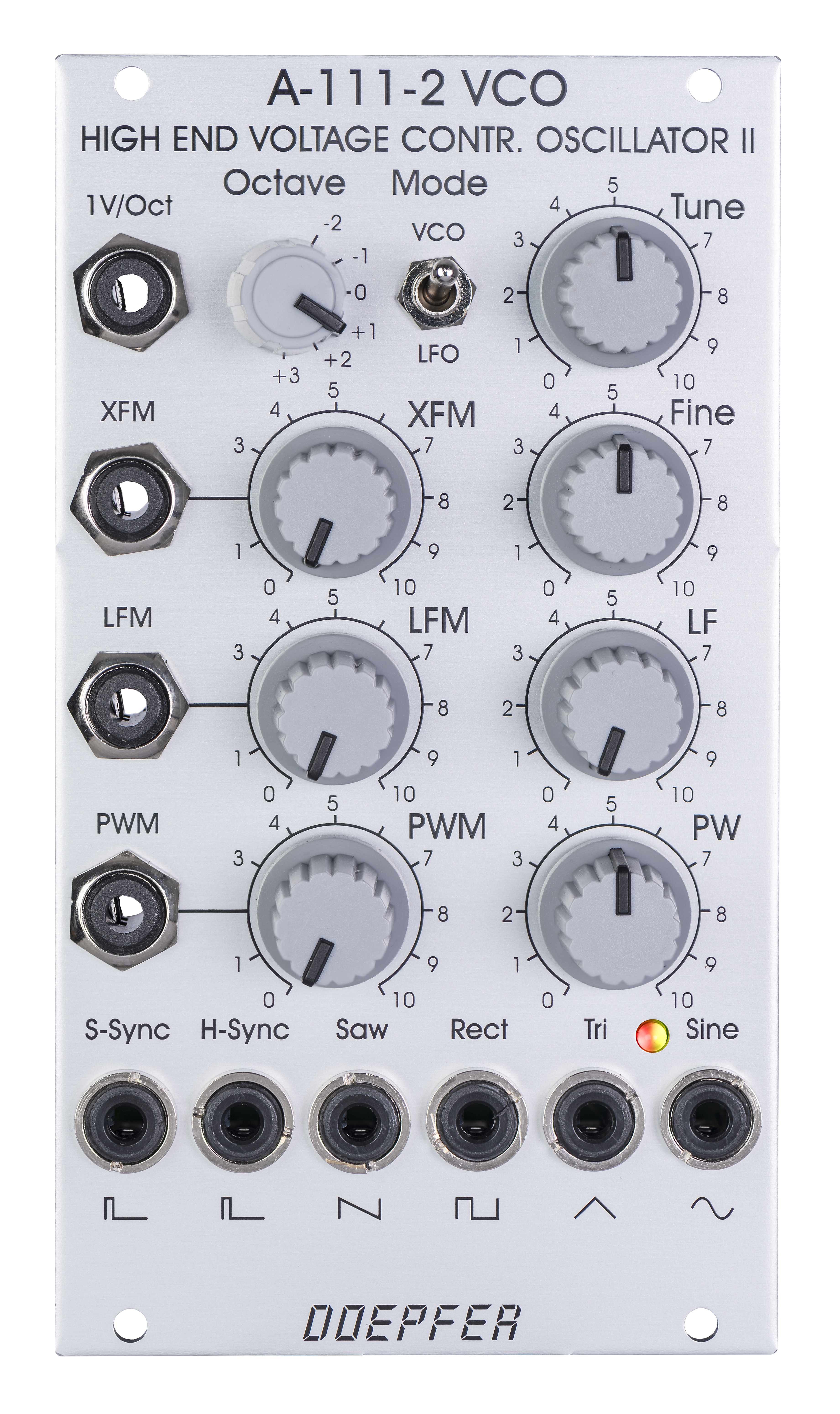
Standard Edition |
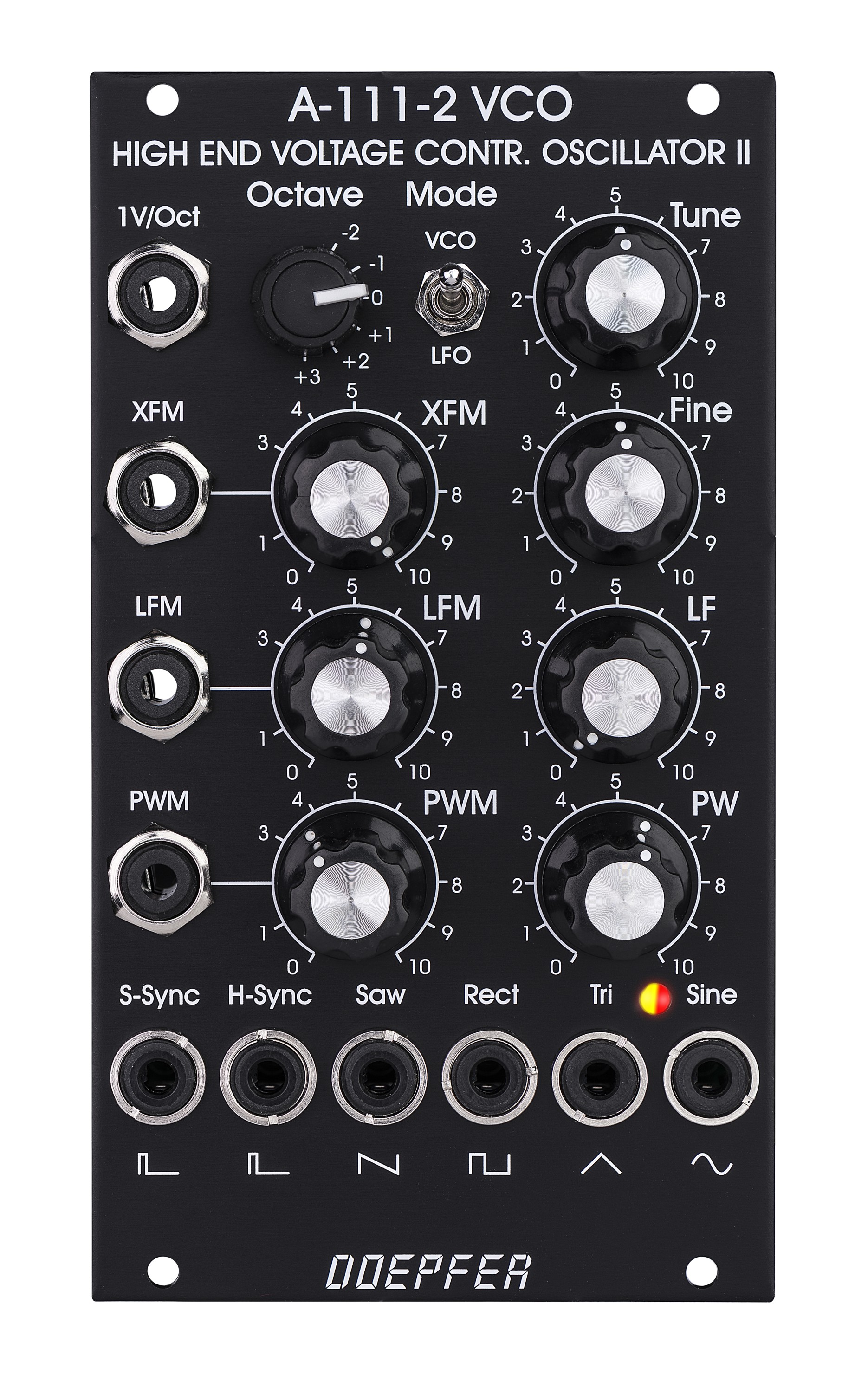
Vintage Edition |
Hier die wichtigsten Eigenschaften des Moduls im Überblick:
- Dreieck-Kern (d.h. die anderen Kurvenformen werden durch Waveshaping aus dem Dreieck abgeleitet)
- voll analoges Design
- min. 15 Oktaven Frequenzumfang (typ. 0.5Hz - 20kHz im VCO-Modus / 0.001Hz - 40Hz im LFO-Modus)
- perfektes 1V/Oktave-Tracking über mindestens 10 Oktaven, typ. 20Hz - 20kHz (der LF-Regler muss für perfektes 1V/Oktave-Tracking auf Rechtsanschlag stehen)
- Exponentielle Einstell-Elemente und Eingänge
für die Frequenz:
- Tune: Bereich mit Hilfe einer Steckbrücke wählbar zwischen ca. +/- 1 Oktave (Jumper JP6 entfernt) oder ca. +/-3 Oktaven (Jumper JP6 aufgesteckt)
- Fine: ca. +/- 1 Halbton
- Octave: Bereichsschalter mit 6 Positionen für 6 Oktaven
- 1V/Oktave Steuereingang
- XFM Eingang mit Abschwächer
- optionaler Zugriff auf die interne Bus CV über interne Steckbrücke (bitte entfernen Sie die Steckbrücke falls diese Funktion nicht genutzt wird, um unerwünschte Frequenzmodulationen zu vermeiden, da die unbeschaltete CV-Leitung der Busplatine als eine Art große Antenne wirkt)
- Lineare Einstell-Elemente und Eingänge für
die Frequenz:
- LF (Manueller Regler für lineare
Frequenzeinstellung: Rechtsanschlag = Standard-Einstellung für VCO-Anwendung
mit 1V/Oktave-Steuerung / Linksanschlag Frequenz nahe 0Hz)
arbeitet als eine Art zusätzlicher Bereichs-Regler für die exponentielle Sektion, für Standard-VCO-Anwendungen mit 1V/Oktave Steuerspannung sollte der Regler aber auf Rechtsanschlag stehen ! - LFM Eingang mit Abschwächer, gleichspannungsgekoppelt
- LF (Manueller Regler für lineare
Frequenzeinstellung: Rechtsanschlag = Standard-Einstellung für VCO-Anwendung
mit 1V/Oktave-Steuerung / Linksanschlag Frequenz nahe 0Hz)
- Einstell-Elemente und Eingänge für die
Pulsbreite des Rechtecks:
- PW (manueller Regler für die Pulsbreite von 0% / Ausgang permanent auf "low" bis zu 100% / Ausgang permanent auf "high")
- PWM Eingang mit Abschwächer
- Hard Sync-Eingang (CEM3340 Hard Sync, siehe untenstehende Skizze)
- Soft Sync-Eingang
- Kurvenform-Ausgänge
- Sägezahn, Ausgangspegel ca. 10Vss (Spannungsbereich ca. 0 ... +10V)
- Rechteck (Pulsbreite gesteuert von den Einstell-Elementen und Eingängen für die Pulsbreite), Ausgangspegel ca. 10Vss (Spannungsbereich ca. 0 ... +10V)
- Dreieck, Ausgangspegel ca. 10Vss (Spannungsbereich ca. -5V ... +5V)
- Sinus, Ausgangspegel ca. 10Vss (Spannungsbereich ca. -5V ... +5V)
- Bereichsschalter um VCO- oder VCLFO-Modus anzuwählen, Frequenzverhältnis zwischen VCO- und LFO-Modus ca. 500 : 1
- Zweifarbige LED-Anzeige des Dreieck-Signals (zur Frequenz-Anzeige im LFO-Modus unter ca. 25 Hz)
- Nahezu perfekte Kurvenformen
- hochwertiger Dreieck-Sinus-Konverter mit nahezu perfekter Sinus-Kurvenforem (vielen Dank an Tim Stinchcombe, der diese Schaltung empfohlen hat)
- der Micro-Präzisions-VCO A-111-3 verwendet die gleiche Grundschaltung, verfügt jedoch über weniger Funktionen
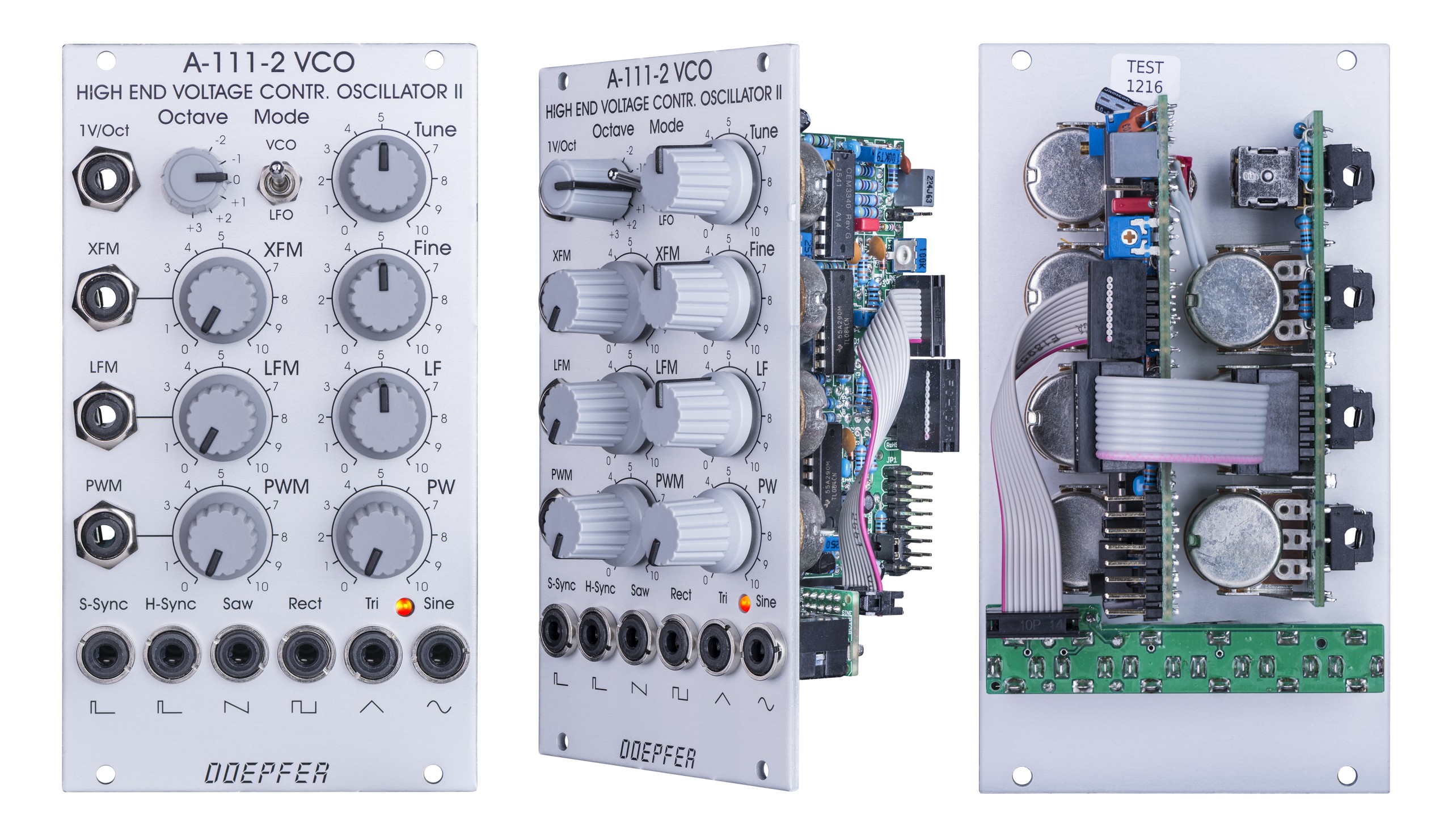
Das folgende Dokument zeigt die Positionen und Funktionen der Steckbrücken und Trimmpotentiometer des Moduls: A111_2_trimming_potentiometers_and_jumpers.pdf
Zusätzliche technische Hinweise:
- Die der 1V/Oct-Buchse zugeführte Steuerspannung wird intern zu der vom Bus kommenden Steuerspannung addiert (abschaltbar durch Entfernen der Steckbrücke JP4). Das Einstecken eines Steckers in die 1V/Oct-Buchse unterbricht also nicht die Bus-CV, oder anders ausgedrückt: die Bus-CV ist nicht auf die 1V/Oct-Buchse normalisiert sondern wird dazu addiert (anders als z.B. bei A-110-1). Das erlaubt beispielsweise das Transponieren einer Sequenz, deren CV über die 1V/Oct-Buchse zugeführt wird, über die Bus-CV..
- Das Modul basiert auf dem VCO-Spezialbaustein CEM3340. Die Hard Sync-Funktion arbeitet hier etwas anders als bei den meisten anderen VCOs. Die untenstehende Skizze aus dem Datenblatt zeigt das genaue Verhalten. Die Funktion ist auch in der Anleitung A111_anl.pdf zu dem nicht mehr lieferbaren Modul A-111-2 beschrieben.
|
|
|
|
|
|
|
Standard Edition |
Vintage Edition |
Here are the most important features of the module:
-
triangle core (i.e. all other waveforms are derived from the triangle by waveshapers)
-
fully analog design
-
min. 15 octaves pitch range (typ. 0.5Hz - 20kHz in VCO mode / 0.001Hz - 40Hz in LFO mode)
-
perfect 1V/octave tracking over min. 10 octaves, typ. 20Hz - 20kHz (control LF has to be fully CW for perfect 1V/octave tracking)
-
exponential frequency controls and inputs:
-
Tune: range can be selected by means of a jumper, about +/- 1 octave (jumper JP6 not installed) or about +/- 3 octaves (jumper JP6 installed)
-
Fine: about +/- 1 semitone range
-
Octave: range switch with 6 positions for 6 octaves
-
1V/octave CV input
-
XFM input with attenuator
-
access to internal bus CV (via jumper, optional, please remove the bus jumper if this feature is not used to avoid unwanted frequency modulation as then the unused CV line of the bus works as a kind of antenna)
-
-
linear frequency controls and inputs:
-
LF (manual linear frequency control: fully CW = standard setting for usual VCO applications, fully CCW: close to 0Hz frequency)
works also as a kind of range control for the exponential section but for standard VCO applications with 1V/octave control voltage the LF control should be fully CW ! -
LFM input with attenuator, DC coupled
-
-
Pulsewidth controls and inputs (for rectangle output):
-
PW (manual pulsewidth control from 0%/output = fixed at "low" state up to 100% / output fixed at "high" state)
-
PWM input with attenuator
-
-
Hard Sync input (CEM3340 hard sync type)
-
Soft Sync input
-
Waveform outputs:
-
Sawtooth, output level ~ 10Vpp (voltage range ~ 0 ... +10V)
-
Rectangle (controlled from pulsewidth section), output level ~ 10Vpp (voltage range ~ 0 ... +10V)
-
Triangle (output level ~ 10Vpp, voltage range ~ -5V ... +5V)
-
Sine (output level ~ 10Vpp, voltage range ~ -5V ... +5V)
-
-
Range switch to select VCO/VCLFO mode, frequency relation between VCO mode and LFO mode about 500 : 1
-
dual color LED display (to display low frequencies below ~ 25 Hz)
-
Nearly "perfect" waveforms
-
high end triangle to sine converter with excellent sine waveshape (thank's to Tim Stinchcombe who recommended this circuit)
-
the micro precision VCO A-111-3 uses the same VCO core as the A-111-2, but has less inputs, outputs and controls
The following document shows the positions and functions of the jumpers and trimming potentiometers of the module: A111_2_trimming_potentiometers_and_jumpers.pdf
Technical remarks:
- The control voltage applied to the socket 1V/Oct is added to the control voltage coming from the bus (interruptible by removing the jumper JP4). Connecting a cable to the socket 1V/Oct does not interrupt the bus CV connection ! I.e. the 1V/Oct socket is not normalled to the bus CV. This allows e.g. transposing sequence CV (applied to the socket 1V/Oct) by the bus CV (e.g. connected to the CV output of a Midi-to-CV interface).
- The module is based on the CEM3340 circuit. The hard sync of the CEM3340 works different compared to most other VCOs. The excerpt from the data sheet below shows the details. The CEM3340 type of hard sync is also explained in the A-111-1 user manual on page 9: A111_man.pdf.
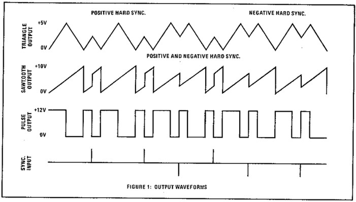
CEM Hard-Sync function
Tiefe/Depth: 55 mm (gemessen ab der Rückseite der Frontplatte / measured from the rear side of the front panel)
Strombedarf/Current: +70mA (+12V) / -50mA (-12V)
Vintage Edition : Euro 295.00
The price in US$ depends upon the exchange rate between Euro and US$ at the payment day.