|
A-111-4 Quad
Precision VCO / Polyphonic VCO
|
Ausführlicher Test aller polyphonen Module: https://youtu.be/5HqfjNGVsDU
Detailed report of all polyphonic modules: https://youtu.be/5HqfjNGVsDU
|
|
|
| click to enlarge |
|
|
|
click to enlarge
|
|
|
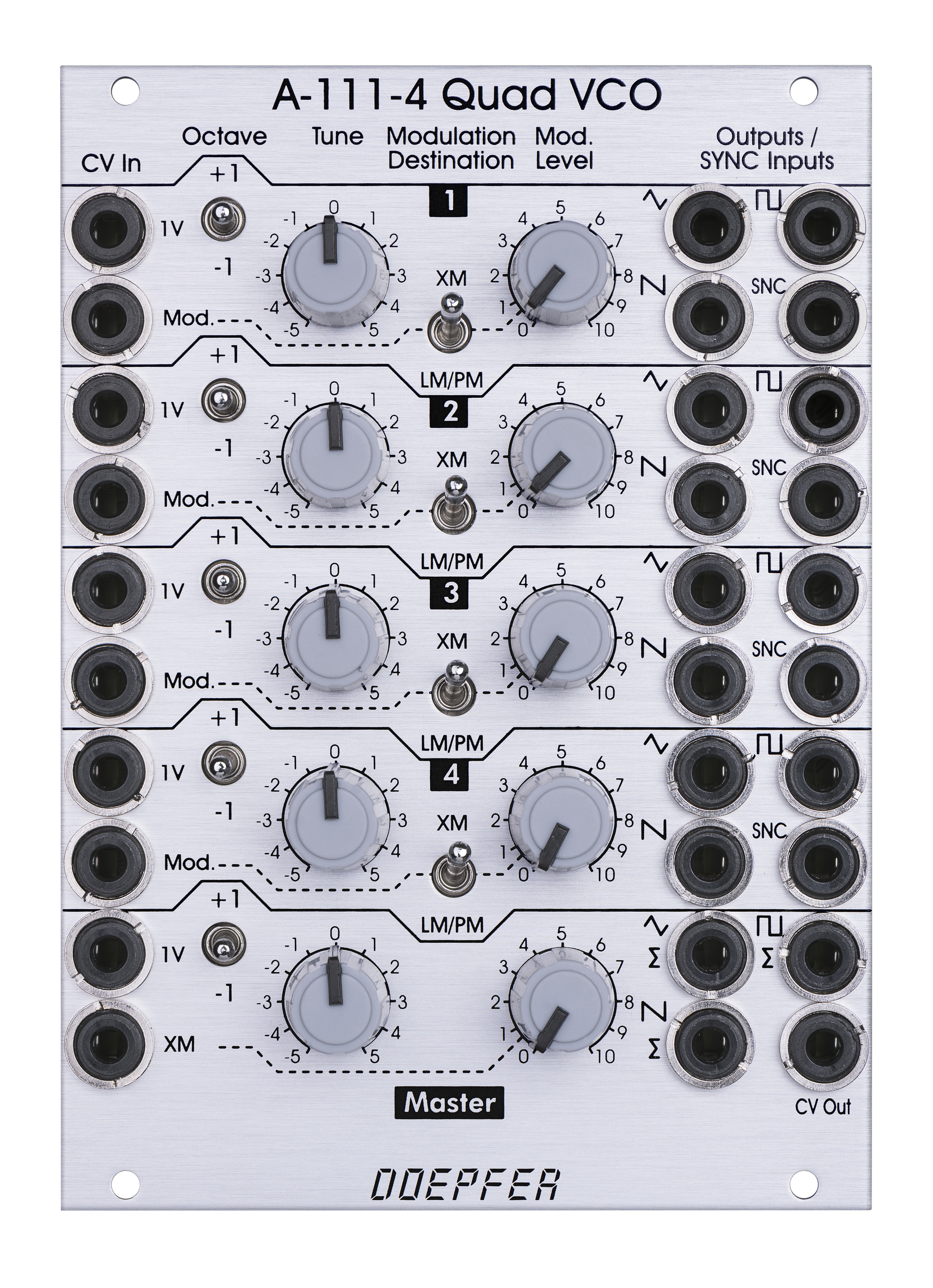
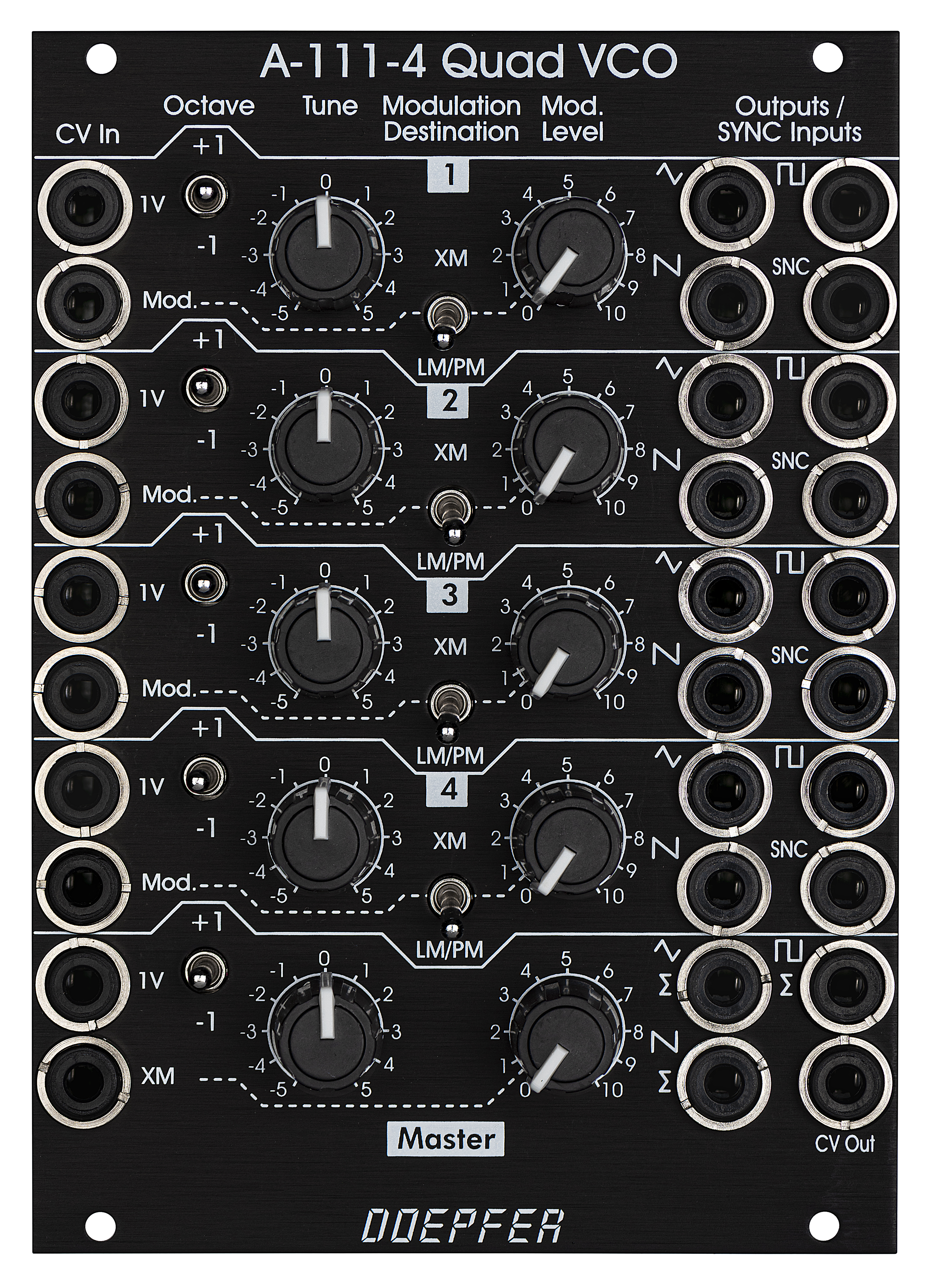
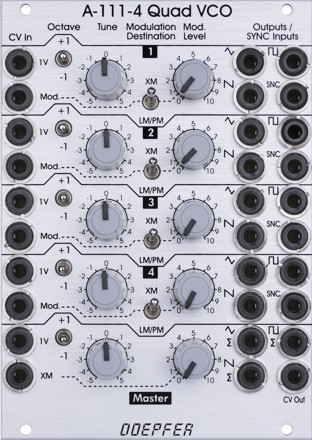
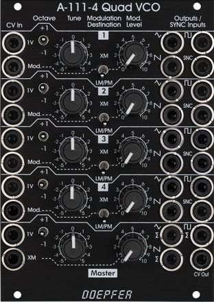
A-111-4
besteht aus vier Präzisions-VCOs. Das Modul verfügt über Bedienelemente
und Ein/Ausgänge für jeden einzelnen VCO. Zusätzlich sind auch
Bedienelemente und Ein/Ausgänge in der Master-Sektion vorhanden, die
allen vier VCOs zugeordnet sind. Im Prinzip besteht A-111-4 aus vier
A-111-3 mit zusätzlichen Ausgangs-Mixern und einer Master-Steuereinheit.
Bedienelemente,
Eingänge und Ausgänge für jeden der vier VCOs:
-
1V/Octave
Steuereingang
-
Oktave-Schalter
(+1/0/-1 Oktave)
-
Tune-Regler
(Reichweite intern mit Hilfe eines Jumper wählbar: ca. 2 Halbtöne / ca. 1
Oktave / ca. 4 Oktaven)
-
Modulations-Steuereingang
-
Schalter
für Modulations-Ziel exponentielle Frequenzmodulation (XM) oder
lineare Frequenzmodulation (LM), mit Hilfe eines internen Jumpers kann
statt linearer FM auch Rechteck-Pulsbreitenmodulation (PM) gewählt
werden
-
Regler
für Modulations-Stärke
-
Dreieck-Ausgang,
ca. 5 Vss Pegel (-2.5V ... +2.5V)
-
Sägezahn-Ausgang,
ca. 5 Vss Pegel (-2.5V ... +2.5V)
-
Rechteck-Ausgang,
ca. 5 Vss Pegel (-2.5V ... +2.5V)
-
Sync-Eingang
(per Jumper Hard- oder Soft-Sync wählbar, CEM3340 Hardsync-Typ,
siehe technische Hinweise weiter unten)
-
min.
10 Oktaven Frequenzumfang (mit entsprechender externer CV)
-
VCO
mit Dreieck-Kern (CEM3340)
-
jeder
VCO besitzt intern eine eigene +/- Stromversorgung für beste
Stabilität und zur Vermeidung ungewünschter Synchronisationseffekte
zwischen den VCOs
Bedienelemente,
Eingänge und Ausgänge der Master-Sektion:
-
1V/Octave
Steuereingang
-
Oktave-Schalter
(+1/0/-1 Oktave)
-
Tune-Regler
(Weite intern mit Hilfe eines Jumper wählbar: ca. 2 Halbtöne / ca. 1
Oktave / ca. 4 Oktaven)
-
Frequenzmodulations-Steuereingang
(FM)
-
Regler
für Modulations-Stärke
-
Dreieck-Summenausgang,
ca. 15 Vss max. Pegel
-
Sägezahn-Summenausgang,
ca. 15 Vss max. Pegel
-
Rechteck-Summenausgang,
ca. 15 Vss max. Pegel
-
sobald
ein Einzelausgang gepatcht wird, wird dieser aus dem Summensignal der
betreffenden Kurvenform entfernt (über Lötbrücken auf der
Leiterplatte kann diese Funktion für jede Buchse abgeschaltet werden,
d.h. das Summensignal enthält dann immer alle Signale unabhängig
davon, ob der betreffende Einzelausgang gepatch ist oder nicht)
-
CV-Ausgang
(gibt die Summe aller Steuerspannungen der Master-Einheit aus)
-
Bus
CV
(optional): die Bus CV wird zu allen anderen Steuerspannungen hinzu addiert, wenn
die betreffende Steckbrücke gesetzt ist, bitte entfernen Sie die Steckbrücke falls
diese Funktion nicht genutzt wird, um unerwünschte Frequenzmodulationen
zu vermeiden, da die unbeschaltete CV-Leitung der Busplatine als eine
Art große Antenne wirkt
Typische
Anwendungen:
-
fett
klingender monophoner VCO mit der Möglichkeit die VCOs auch auf
Intervalle einzustellen
-
paraphone
Patches (alle vier VCOs durchlaufen eine gemeinsame VCF/VCA-Einheit) in
Kombination mit dem polyphonen Midi/USB-CV-Interface A-190-5
-
vollpolyphone
Patches in Kombination mit dem polyphonen Midi/USB-CV-Interface A-190-5
-
komplexe
VCO-Patches mit bis zu vier VCOs mit Hilfe von Frequenzmodulationen
(exponentiell und linear) und den Sync-Funktionen
Das folgende Dokument zeigt
die Positionen und Funktionen der Trimmpotentiometer und Steckbrücken: A111_4_trimming_potentiometers_and_jumpers.pdf
Wir weisen vorsorglich darauf hin, dass falsche Justierungen durch das
Verändern der Trimmpotentiometer-Einstellungen seitens des Kunden nicht
von der Garantie abgedeckt sind. In diesem Fall müssen wir ggf. die
Arbeitszeit für die Neujustierung des Moduls in Rechnung stellen !
Das folgende Dokument enthält Hinweise zur internen Vorverdrahtung der
polyphonen Module A100_internal_polyphonic_wiring.pdf
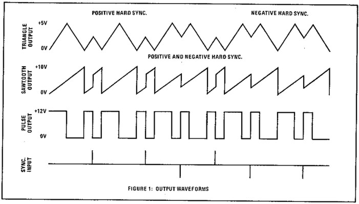
Technische Hinweise:
Das Modul basiert auf dem Baustein CEM3340. Die Hard-Sync-Funktion des CEM3340
arbeitet anders als die vieler anderer VCOs. Ein Auszug aus dem Datenblatt zeigt
die Details:
Die
Hard-Sync-Funktion des CEM3340 ist auch in der Anleitung zum A-111-1 auf
den Seiten 8-9 erläutert: A111_anl.pdf
|
|
|
|
click to enlarge
|
|
|
|
click to enlarge
|
|
|
|
A-111-4
contains four precision VCOs and has individual controls, inputs and
outputs for each VCO available as well as a common control and output unit.
After all the A-111-4 is very similar to four A-111-3
without LFO mode but built in output mixers for the three waveforms, and a
master unit for all four VCOs.
Controls,
inputs and outputs for each of the four VCOs:
-
1V/Octave
CV input
-
Octave
switch (+1 / 0 / -1 octave)
-
Tune
control (range internally adjustable by jumpers: ~ 2 semitones / ~ 1
octave / ~ 4 octaves)
-
Modulation
CV input
-
Modulation
destination:
-
upper
position: exponential frequency modulation (XM)
-
lower
position: linear frequency modulation (LM) or pulsewidth
modulation of the
rectangle (PM), selectable via internal jumper
-
Frequency Modulation (FM) or Pulsewidth Modulation of the
rectangle (PWM)
-
Modulation
intensity
-
Triangle
output, about 5 Vpp level (-2.5V ... +2.5V)
-
Sawtooth
output, about 5 Vpp level (-2.5V ... +2.5V)
-
Rectangle
output (about 50% without external PWM), about 5 Vpp level (-2.5V ...
+2.5V)
-
Sync
input (hard or soft sync internally selectable via jumper, CEM3340
hard sync type, see technical remarks below)
-
min.
10 octaves range (with appropriate external
CV)
-
CEM3340
based VCO (triangle core)
-
each
VCO has it's own separate internal +/- power supply for each for best
stability and the prevention of unwanted synchronisation of the VCOs
Controls,
inputs and outputs of the master section:
-
1V/Octave
CV input
-
Octave
switch (+1 / 0 / -1 octave)
-
Tune
control (range internally adjustable by jumpers: 2 semitones / 1
octave / 4 octaves)
-
Frequency
Modulation CV input (FM)
-
FM
intensity
-
Triangle
sum output, about 15 Vpp level
-
Sawtooth
sum output, about 15 Vpp level
-
Rectangle
sum output, about 15 Vpp level
-
as
soon as the single waveform output of a VCO is patched this waveform
of the VCO in question is removed from the sum (this function can be
turned off for each single output socket by means of solder brigdes on
the pc board, i.e. the sum contains then all signals independent of
the patching of the single output)
-
CV
output (outputs the sum CV that is used to control all four VCOs)
-
bus
CV (via jumper, optional): the bus CV is added to all other
control voltages when the corresponding jumper is installed, please remove the bus jumper if this feature is not used to
avoid unwanted frequency modulation as then the unused CV line of the
bus works as a kind of antenna
Typical
applications:
-
fat
sounding monophonic VCO with the possibility to adjust any intervals
-
paraphonic
patches in combination with the polyphonic CV interface A-190-5
(all four VCOs processed by one VCF/VCA)
-
full
polyphonic patches in combination with the polyphonic CV interface A-190-5
and four complete VCF/VCA sections
-
complex
VCO patches with up to four VCOs by means of the frequency modulation
features (exponential an linear) and the sync functions
The following document shows the
positions and functions of the jumpers and trimming potentiometers of the
module: A111_4_trimming_potentiometers_and_jumpers.pdf
Pay attention that faulty adjustments caused by the user are not
covered by warranty. In this case the working time required to
re-establish the correct adjustment has to be charged.
The following document contains basic information about the internal
pre-wiring of polyphonic modules: A100_internal_polyphonic_wiring.pdf
Technical remarks:
The module is based on the CEM3340 circuit. The hard sync of the CEM3340 works
different compared to most other VCOs. The excerpt from the data sheet shows the
details:
The
CEM3340 type of hard sync is also explained in the A-111-1 user manual on page
9: A111_man.pdf.
|
|
|
Breite/Width:18HP / 91.3 mm
Tiefe/Depth: 40 mm
(gemessen ab der Rückseite der Frontplatte / measured from the rear side
of the front panel)
Strombedarf/Current: +120mA (+12V) / -100mA (-12V)
|
|
Preise
/ Prices:
Standard Version
:
Euro 440.00
Vintage
Edition : Euro 460.00
The price in US$
depends upon the exchange rate between Euro and US$ at the payment day.
|
|
|
Blockschaltbild / Sketch
|
|
| Vorgeschichte
der A-111-4 Entwicklung / History
of the A-111-4 development |
|
|
|
A-111-4 Quad
Precision VCO
Vorankündigung / preliminary
|
|
|
A-111-4
besteht aus vier Präzisions-VCOs. Das Modul verfügt über Bedienelemente
und Ein/Ausgänge für jeden einzelnen VCO. Zusätzlich sind auch
Bedienelemente und Ein/Ausgänge in der Master-Sektion vorhanden, die
allen vier VCOs zugeordnet sind. Im Prinzip besteht A-111-4 aus vier
A-111-3 mit zusätzlichen Ausgangs-Mixern und einer Master-Steuereinheit.
Bedienelemente,
Eingänge und Ausgänge für jeden der vier VCOs:
-
1V/Octave
Steuereingang
-
Oktave-Schalter
(+1/0/-1 Oktave)
-
Tune-Regler
(Weite intern mit Hilfe eines Jumper wählbar: ca. 2 Halbtöne / ca. 1
Oktave / ca. 4 Oktaven)
-
Modulations-Steuereingang
-
Schalter
für Modulations-Ziel Frequenzmodulation
(FM) oder Pulsbreitenmodulation des Rechtecks (PWM)
-
Regler
für Modulations-Stärke
-
Dreieck-Ausgang
-
Sägezahn-Ausgang
-
Rechteck-Ausgang
-
Sync-Eingang
(per Jumper Hard- oder Soft-Sync wählbar, CEM3340
Hardsync-Typ)
-
min.
10 Oktaven Frequenzumfang (mit entsprechender externer CV)
-
VCO
mit Dreieck-Core (CEM3340)
-
jeder
VCO besitzt intern eine eigene +/- Stromversorgung für beste
Stabilität und zur Vermeidung ungewünschter Synchronisationseffekte
zwischen den VCOs
Bedienelemente,
Eingänge und Ausgänge der Master-Sektion:
-
1V/Octave
Steuereingang
-
Oktave-Schalter
(+1/0/-1 Oktave)
-
Tune-Regler
(Weite intern mit Hilfe eines Jumper wählbar: ca. 2 Halbtöne / ca. 1
Oktave / ca. 4 Oktaven)
-
Frequenzmodulations-Steuereingang
(FM)
-
Regler
für Modulations-Stärke
-
Dreieck-Summenausgang
-
Sägezahn-Summenausgang
-
Rechteck-Summenausgang
-
sobald
ein Einzelausgang gepatcht wird, wird dieser aus dem Summensignal der
betreffenden Kurvenform entfernt (über Lötbrücken auf der
Leiterplatte kann diese Funktion für jede Buchse abgeschaltet werden,
d.h. das Summensignal enthält dann immer alle Signale unabhängig
davon, ob der betreffende Einzelausgang gepatch ist oder nicht)
-
CV-Ausgang
(gibt die Summe aller Steuerspannungen der Master-Einheit aus)
-
Bus
CV (wählbar über Jumper)
Änderungen
Prototyp 2 gegenüber Prototyp 1:
-
Kippschalter
anders angeordnet, damit man die Schalter leichter erreichen kann,
ohne die Reglerstellungen zu verändern. Die Abstände sind im
Gegensatz zu anderen A-100-Modulen immer noch klein, aber wir mussten
einen Kompromiss zwischen Bedienbarkeit und dem Wunsch vieler finden,
die möglichst viele Funktionen auf kleiner Fläche wünschen.
-
Modulations-Ziel:
-
obere
Stellung: exponentielle Frequenzmodulation (jetzt mit XM
bezeichnet)
-
untere
Stellung: lineare
Frequenzmodulation (LM) oder Pulsbreitenmodulation des
Rechtecks (PM), wählbar über internen Jumper.
Änderungen
Prototyp 3 gegenüber Prototyp 2:
-
Abstände
zwischen den Schaltern und Reglern vergrößert, um einen besseren
Bedienkomfort zu erhalten
-
die
Frontplattenbreite erhöht
sich dadurch auf 18TE (91,3 mm)
Typische
Anwendungen:
-
fett
klingender monophoner VCO mit der Möglichkeit die VCOs auch auf
Intervalle einzustellen
-
paraphone
Patches (alle vier VCOs durchlaufen eine gemeinsame VCF/VCA-Einheit) in
Kombination mit dem polyphonen Midi/USB-CV-Interface A-190-5
-
vollpolyphone
Patches in Kombination mit dem polyphonen Midi/USB-CV-Interface A-190-5
-
komplexe
VCO-Patches mit bis zu vier VCOs mit Hilfe von Frequenzmodulationen
(exponentiell und linear) und den Sync-Funktionen
|
|
|
|
|
A-111-4
contains four precision VCOs and has individual controls, inputs and
outputs for each VCO available as well as a common control and output unit.
After all the A-111-4 is very similar to four A-111-3
without LFO mode but built in output mixers for the three waveforms, and a
master unit for all four VCOs.
Controls,
inputs and outputs for each of the four VCOs:
-
1V/Octave
CV input
-
Octave
switch (+1 / 0 / -1 octave)
-
Tune
control (range internally adjustable by jumpers: ~ 2 semitones / ~ 1
octave / ~ 4 octaves)
-
Modulation
CV input
-
Modulation
destination Frequency Modulation (FM) or Pulsewidth Modulation of the
rectangle (PWM)
-
Modulation
intensity
-
Triangle
output
-
Sawtooth
output
-
Rectangle
output (about 50% without external PWM)
-
Sync
input (hard or soft sync internally selectable via jumper, CEM3340
hard sync type)
-
min.
10 octaves range (with appropriate external
CV)
-
CEM3340
based VCO (triangle core)
-
each
VCO has it's own separate internal +/- power supply for each for best
stability and the prevention of unwanted synchronisation of the VCOs
Controls,
inputs and outputs of the master section:
-
1V/Octave
CV input
-
Octave
switch (+1 / 0 / -1 octave)
-
Tune
control (range internally adjustable by jumpers: 2 semitones / 1
octave / 4 octaves)
-
Frequency
Modulation CV input (FM)
-
FM
intensity
-
Triangle
sum output
-
Sawtooth
sum output
-
Rectangle
sum output
-
as
soon as the single waveform output of a VCO is patched this waveform
of the VCO in question is removed from the sum (this function can be
turned off for each single output socket by means of solder brigdes on
the pc board, i.e. the sum contains then all signals independent of
the patching of the single output)
-
CV
output (outputs the sum CV that is used to control all four VCOs)
-
bus
CV (selectable via jumper)
Modifications
prototype 2 vs. prototype 1:
Modifications
prototype 3 vs. prototype 2:
-
distances
between the switches and knobs increased to improve the ease of use
-
thereby
the width of the front panel had to be increased to 18HP
(91,3 mm)
Typical
applications:
-
fat
sounding monophonic VCO with the possibility to adjust any intervals
-
paraphonic
patches in combination with the polyphonic CV interface A-190-5
(all four VCOs processed by one VCF/VCA)
-
full
polyphonic patches in combination with the polyphonic CV interface A-190-5
and four complete VCF/VCA sections
-
complex
VCO patches with up to four VCOs by means of the frequency modulation
features (exponential an linear) and the sync functions
|
|