A-141-4 Quad Poly VCADSR
Detailed report of all polyphonic modules: https://youtu.be/5HqfjNGVsDU
|
click to enlarge |
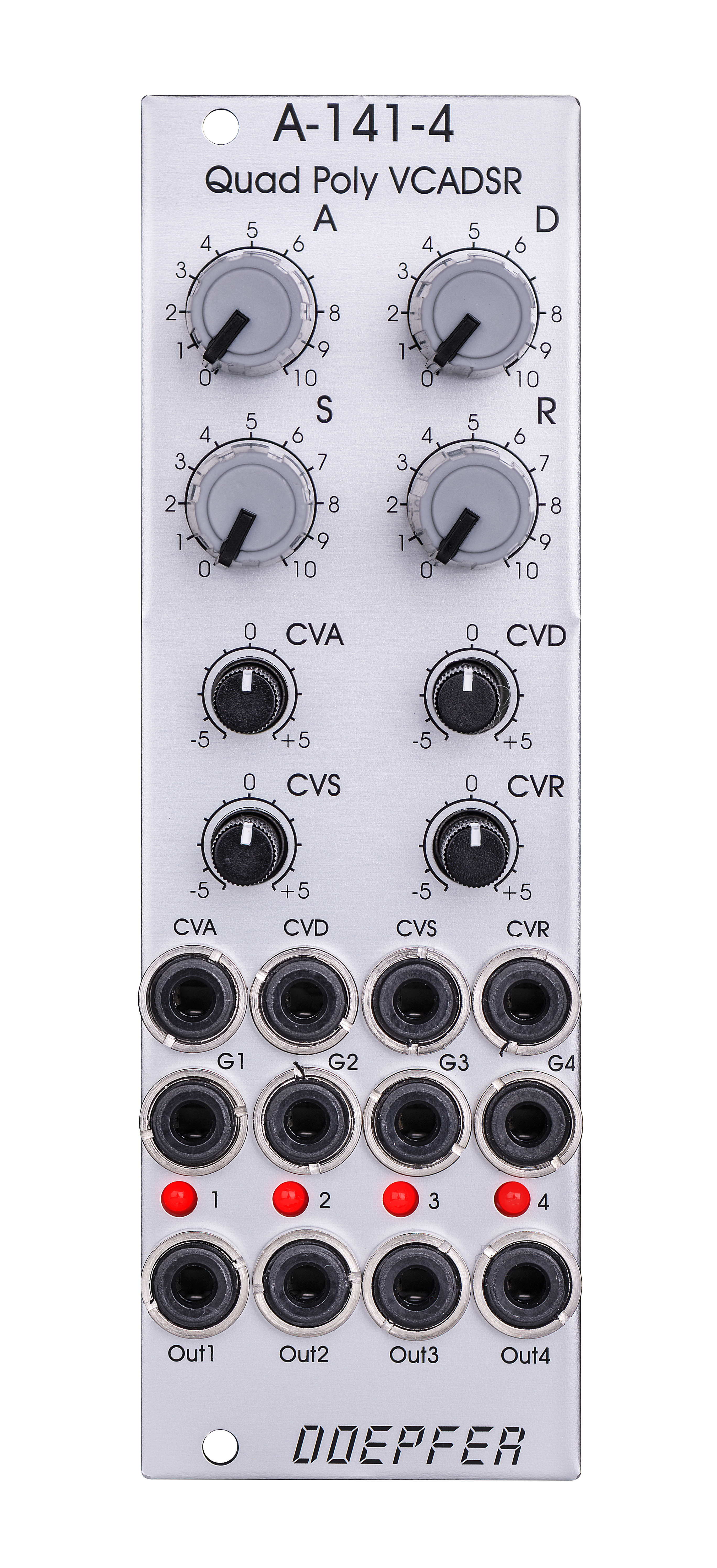 |
Folgende Bedienelemente und Ein/Ausgänge stehen zur Verfügung:
- Attack (manuelle Einstellung)
- Decay (manuelle Einstellung)
- Sustain (manuelle Einstellung)
- Release (manuelle Einstellung)
- CVA Regler (Polarizer für den Attack CV-Eingang)
- CVD Regler (Polarizer für den Decay CV-Eingang)
- CVS Regler (Polarizer für den Sustain CV-Eingang)
- CVR Regler (Polarizer für den Release CV-Eingang)
- CVA-Buchse (Attack CV-Eingang)
- CVD-Buchse (Decay CV-Eingang)
- CVS-Buchse (Sustain CV-Eingang)
- CVR-Buchse (Release CV-Eingang)
- Gate-Eingänge 1 - 4, Pegel min. +5 / max. +12V
- Hüllkurven-Ausgänge 1 - 4 (Out 1 - 4), Ausgangspegel 0...+10V
- LED Anzeigen 1- 4 (zeigen den Verlauf der Hüllkurve an)
Die Ausgangsspannung der Hüllkurven beträgt 0 -
10V.
Die Attack/Decay/Release-Zeiten liegen ca. zwischen 1ms und 30s.
Die Gate-Pegel im "high"-Zustand müssen min. +5V betragen (bis +12V),
im "low"-Zustand 0V. Als Gate sind nur Signale mit schneller
Anstiegsflanke ("Rechteck") geeignet. Signale mit langsam
veränderlichen Pegeln (z.B. Dreieck) sind als Gate-Signale nicht geeignet.
Funktion der Polarizer:
- Eine an der Buchsen CVA/CVD/CVR anliegende positive Steuerspannung verkürzt die mit den Reglern A/D/R eingestellt Zeit, wenn sich der Regler CVA/CVD/CVR rechts von der Mittelstellung befindet.
- Eine an der Buchsen CVA/CVD/CVR anliegende positive Steuerspannung verlängert die mit den Reglern A/D/R eingestellt Zeit, wenn sich der Regler CVA/CVD/CVR links von der Mittelstellung befindet.
- Eine an der Buchse CVS anliegende positive Steuerspannung verringert den mit dem Regler S eingestellten Wert, wenn sich der Regler CVS rechts von der Mittelstellung befindet.
- Eine an der Buchse CVS anliegende positive Steuerspannung erhöht den mit dem Regler S eingestellten Wert, wenn sich der Regler CVS links von der Mittelstellung befindet.)
Anwendung: Polyphone Patches (vier Hüllkurven-Generatoren mit den gleichen Hüllkurven-Parametern zur Steuerung von VCFs, VCAs oder anderen Modulen)
Das folgende Dokument zeigt
die Positionen und Funktionen der Steckbrücken und Stiftleisten: A141_4_connectors_and_jumpers.pdf
Das folgende Dokument enthält Hinweise zur internen Vorverdrahtung der
polyphonen Module A100_internal_polyphonic_wiring.pdf
The module has these controls and in/outputs are available:
- Attack (manual control)
- Decay (manual control)
- Sustain (manual control)
- Release (manual control)
- CVA control (polarizer for Attack CV input)
- CVD control (polarizer for Decay CV input)
- CVS control (polarizer for Sustain CV input)
- CVR control (polarizer for Release CV input)
- CVA socket (Attack CV input)
- CVD socket (Decay CV input)
- CVS socket (Sustain CV input)
- CVR socket (Release CV input)
- Gate inputs 1 - 4, min. level +5V, max. level +12V
- Envelope outputs 1 - 4
- LED displays 1- 4 (envelope display)
The output voltage range for each envelope is 0 - 10V.
The time range of Attack/Decay/Release is about 1ms to 30s.
The gate levels in the "high" state have to be at least +5V (up to
+12V). The "low" state has to be 0V or less. Only signals with fast
rising slopes ("rectangle type") are suitable as gate signals. Slowly
changing signals (e.g. triangle) cannot be used as gate signals.
Function of the polarizers:
- a positive control voltage applied to the socket CVA/CVD/CVR reduces the time adjusted by the manual A/D/R controls when the CVA/CVD/CVR control is right from the center position
- a positive control voltage applied to the socket CVA/CVD/CVR increases the time adjusted by the manual A/D/R controls when the CVA/CVD/CVR control is left from the center position
- a positive control voltage applied to the socket CVA reduces the sustain value adjusted by the manual S control when the CVS control is right from the center position
- a positive control voltage applied to the socket CVA increases the sustain value adjusted by the manual S control when the CVS control is left from the center position
Application:polyphonic patches (four envelope generators with the same envelope parameters to control four VCFs, VCAs or other modules)
The following document shows the
positions and functions of the jumpers and pin headers of the
module: A141_4_connectors_and_jumpers.pdf
The following document contains basic information about the internal
pre-wiring of polyphonic modules: A100_internal_polyphonic_wiring.pdf
Breite/Width: 8 TE / 8 HP / 40.3 mm
Tiefe/Depth: 45 mm (gemessen ab der Rückseite der Frontplatte / measured
from the rear side of the front panel)
Strombedarf/Current: +70mA (+12V) / -60mA
(-12V)
The price in US$ depends upon the exchange rate between Euro and US$ at the payment day.