A-135-4 Voltage Controlled Performance Mixer Modules
 click to enlarge |
 click to enlarge |
 click to enlarge |
 click to enlarge |
 |
 |
 |
 |
|
|
|||
 |
|||
| Blockschaltbild A-135-4A/B (ein Kanal gezeichnet) | |||
Beschreibung der Module im einzelnen:
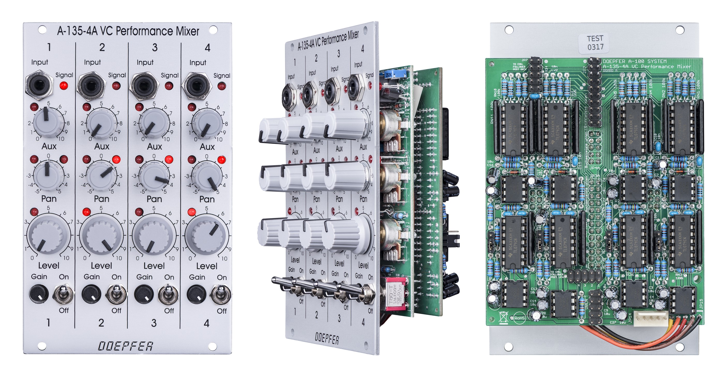
A-135-4A
A-135-4A ist das Hauptmodul. Es arbeitet im
Prinzip wie das Modul A-138p, jedoch sind hier alle
Parameter - mit Ausnahme von Gain - spannungsgesteuert. Die Frontplatten von
A-135-4A und A-138p sind sehr ähnlich. Der Hauptunterschied besteht darin, dass
beim A-135-4A die Funktionen von Level, Pan und Aux zusätzlich mit LEDs
angezeigt werden. Ohne die LED-Anzeigen hätte man keine optische Kontrolle
über den tatsächlichen Wert des betreffenden Parameters, da dieser nicht nur
aus der Position des manuellen Reglers abgeleitet wird, sondern die externe,
über das Modul A-135-4B zugeführte Steuerspannung hinzu addiert oder subtrahiert wird.
A-135-4A beinhaltet pro Kanal vier lineare, spannungsgesteuerte Verstärker (VCA): einen für die Haupt-Lautstärke
(Level),
zwei für Panorama links/rechts und einen für den Aux-Weg. Alle
Steuerkennlinien sind linear. Insgesamt sind in dem Modul 16 VCAs verbaut. Es kommen hochwertige spannungsgesteuerte
Verstärker der Fa. Curtis (CEM3381) mit linearer Steuerkennlinie zum Einsatz. Die LEDs zeigen dabei den aktuellen
Verstärkungsfaktor eines jeden der 16 VCAs grob an.
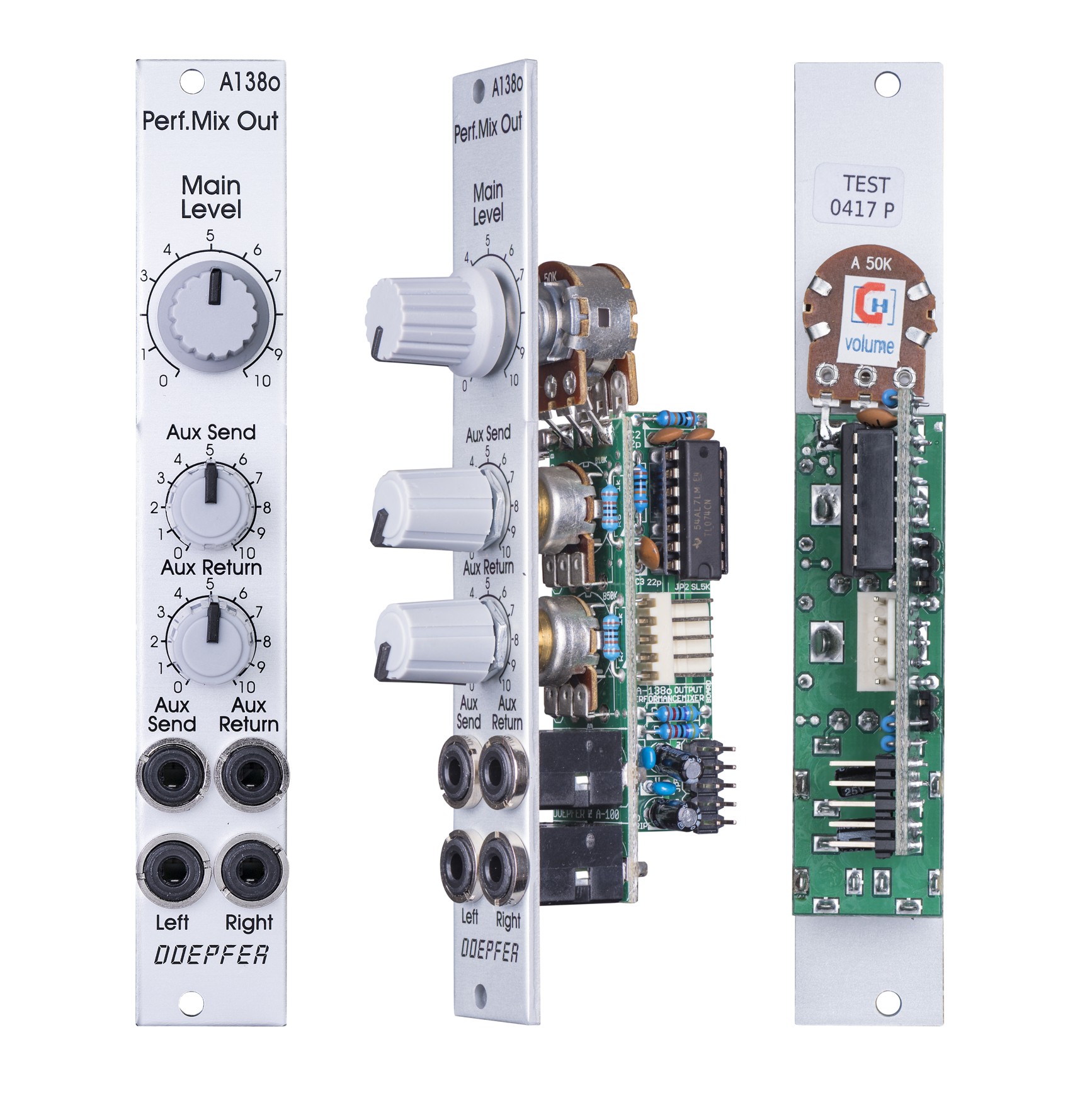
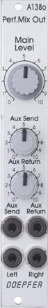
Als Ausgangs-Einheit wird das Modul A-138o verwendet. A-135-4A und A-138p können auch gemischt zusammen mit einem gemeinsamen
Ausgangsmodul A-138o betrieben werden (beispielsweise
vier rein manuell bedienbare und vier spannungsgesteuerte Mixer-Eingänge).
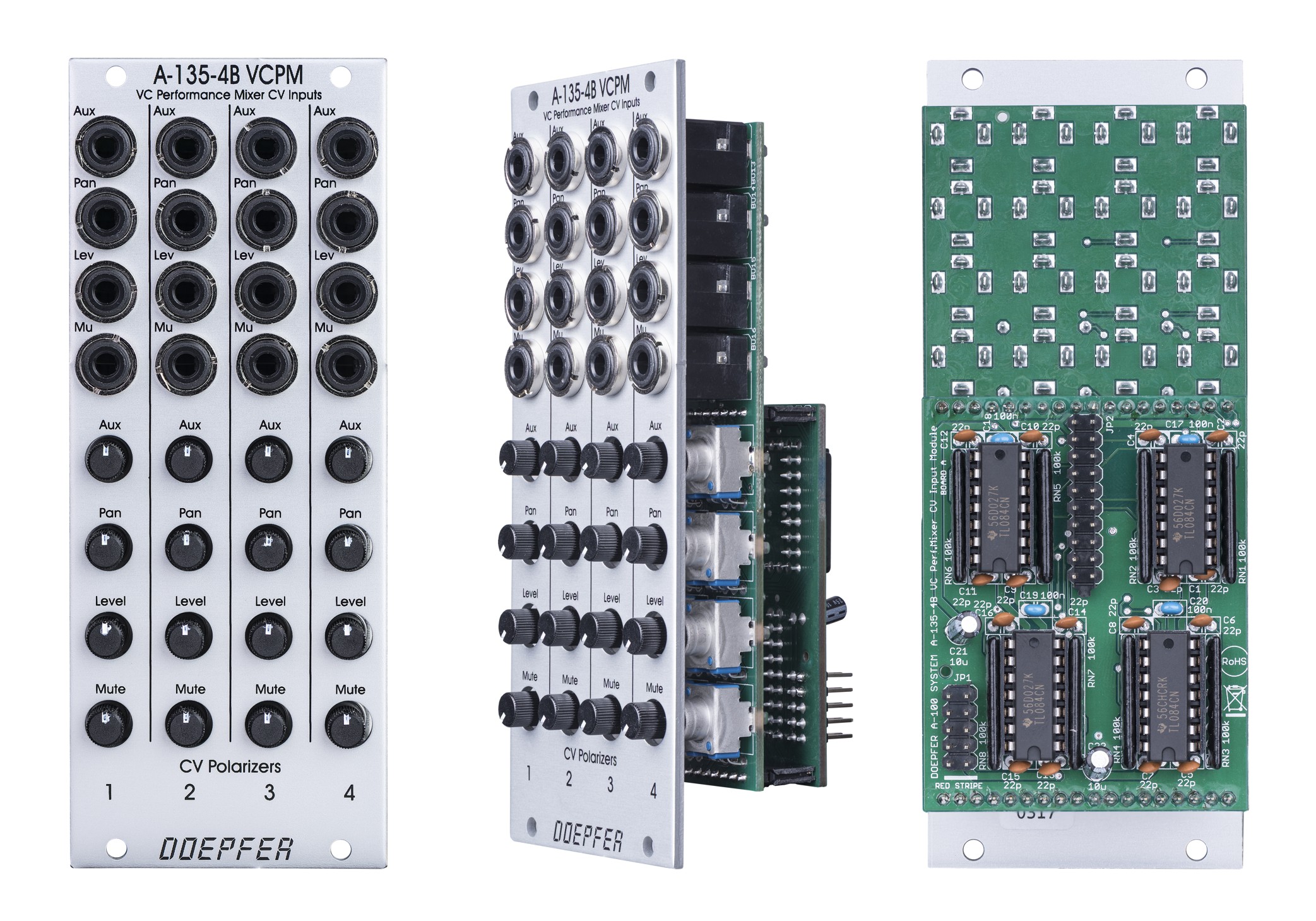
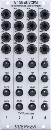
A-135-4B
Über dieses Modul werden dem Hauptmodul die externen Steuerspannungen zugeführt. Folgende Parameter sind für jeden Kanal getrennt spannungssteuerbar:
- Level (Haupt-Lautstärke)
- Panorama
- Aux-Weg
- Mute
Für jede Steuerspannung steht eine Buchse und ein Polarizer zur Verfügung, damit die Beeinflussung des betreffenden Parameters über die extern zugeführte Steuerspannung wahlweise positiv oder negativ und in wählbarer Dosierung eingestellt werden kann (die Polarizer-Funktion ist etwas ausführlicher bei dem Modul A-138c beschrieben). Die externe Steuerspannung wird dabei zu der manuellen Einstellung des betreffenden Parameters am Hauptmodul A-135-4A addiert und die Summe des Steuersignals mit einer (Level, Aux) bzw. zwei LEDs (Panorama) dort angezeigt. Die Grafik auf der linken Seite zeigt einen Kanal von A-135-4A/B als Blockschaltbild.
Der CV-Eingang für Mute arbeitet im Prinzip wie der CV-Eingang für Level, jedoch mit umgekehrter Polarität. Außerdem ist der Mute-Steuereingang um einen Faktor 2 empfindlicher. Typischerweise wird der Regler für den Mute-CV-Eingang auf Rechtsanschlag gestellt. Eine (Gate-) Spannung von +2,5V oder mehr schaltet dann den betreffenden Eingang stumm. Falls die Mute-Funktion nicht benötigt wird, kann der Mute-Steuereingang auch als zweiter Steuereingang für Level verwendet werden (mit umgekehrter Polarität und doppelter Empfindlichkeit gegenüber den regulären Level-Steuereingang).
Die Verbindung zwischen A-135-4A und A-135-4B erfolgt intern über ein 20-poliges Flachbandkabel. Das Kabel kann auch länger ausgeführt werden, so dass das Modul für die CV-Eingänge nicht unbedingt neben dem Hauptmodul angeordnet werden muss (sondern z.B. auch in der Reihe darunter oder darüber).
A-135-4A und A-135-4B sind nur zusammen lieferbar, da ein einzelner Betrieb nicht sinnvoll ist.
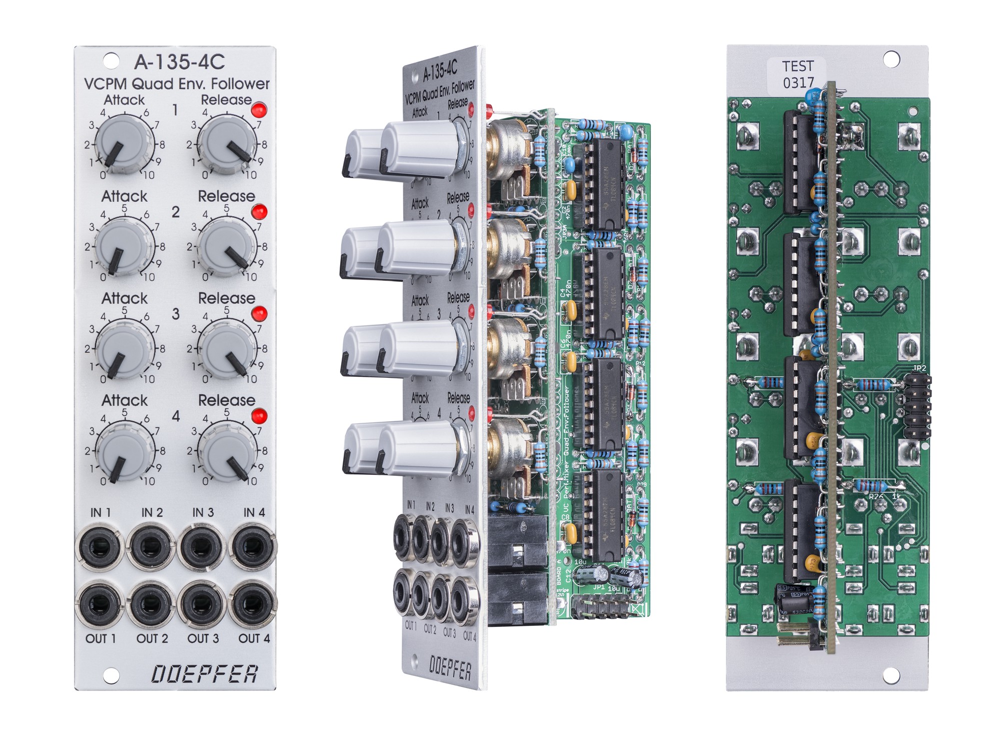
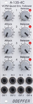
A-135-4C
A-135-4C ist ein 4-facher Hüllkurvenfolger
(Envelope-Follower) mit getrennt einstellbaren Attack- und Release-Zeiten für
jeden Kanal. Das Modul ist dazu gedacht aus den vier Eingangssignalen des A-135-4A Hüllkurve-Signale abzuleiten, die dann wiederum zur Steuerung von
Parametern des A-135-4A über das Modul A-135-4B verwendet werden.
Anwendungsbeispiele hierfür sind Ducking (d.h. das Signal eines Kanals wird
dazu verwendet ein anderes mehr oder weniger stark leiser zu machen), sowie
Kompressor- oder Expander-Funktionen. Hierzu wird der gewünschte Ausgang des
A-135-4C mit dem betreffenden Steuereingang des A-135-4B verbunden und die Stärke
und Polarität der Parameter-Beeinflussung mit dem zugehörigen Regler am A-135-4B eingestellt.
Das Modul A-135-4C besitzt vier Eingänge für die Audio-Signale und vier
Ausgänge für die Hüllkurven-Signale. Die Eingänge können mit Hilfe der
Schaltkontakte der Eingangsbuchsen über ein 10-poliges Verbindungskabel auf die
vier Audio-Eingänge das A-135-4A intern normalisiert werden. Es kann dabei
gewählt werden, ob die Audiosignale direkt an den Eingangsbuchsen des A-135-4A
abgegriffen werden oder nach dem Gain-Regler oder nach dem Level-VCA (drei
verschiedene Steck-Möglichkeiten). Das interne Verbindungskabel kann auch
länger ausgeführt werden, so dass das Envelope-Follower-Modul nicht unbedingt
in der Nähe des Hauptmoduls angeordnet werden muss.
Wird ein Patch-Kabel in eine der Eingangsbuchsen des A-135-4C gesteckt, so wird
die interne Verbindung zum A-135-4A aufgetrennt und das Modul kann für andere
Aufgaben innerhalb des A-100 genutzt werden - beispielsweise als einfaches Attack/Release-Modul
mit Gate-Signalem als Eingang oder als Hüllkurvenfolger für andere Signale.
Der Ausgangspegel hängt vom Eingangspegel und der Kurvenform des
Eingangssignals ab und liegt bei ca. 50% des Spitze-Spitze-Wertes des
Eingangssignals. Durch Ändern eines Widerstandes kann die interne Verstärkung
aber bei Bedarf erhöht oder erniedrigt werden.
Die vier vom Modul erzeugten Hüllkurven werden mit Hilfe von LEDs
angezeigt.
Die Attack/Release-Zeiten können in einem Bereich von ca. 0,01s bis 0,5s
eingestellt werden.
A-135-4C ist zum Betrieb von A-135-4A/B nicht erforderlich, sondern wird nur für
die oben erwähnten Funktionen (z.B. Ducking, Kompressor, Expander) benötigt.
Die Zeitkonstante eines jeden der Hüllkurvenfolger liegt bei ca. 10ms wird
durch den Wert eines Kondensators bestimmt. Durch Ändern des Kondensatorwertes
kann die Zeitkonstante verkürzt (z.B. wenn ein sehr schnelles Ansprechverhalten
gewünscht wird) oder auch verlängert werden.
Weitere technische Hinweise:
Auf dem Modul A-135-4A steht weiterer interner Stecker zur Verfügung, der zur
Normalisierung der Audio-Eingänge verwendet werden kann. Falls man die
Anordnung der Eingangsbuchsen an der Oberseite des Moduls als ungünstig
empfindet, so können hierüber 4 Buchsen an anderer Stelle angeordnet werden,
die dann als Audio-Eingänge für A-135-4A dienen. Bei entsprechender Nachfrage
wäre ein entsprechendes, passives Zusatzmodul (A-135-4?) denkbar.
Die Audio-Eingänge des A-135-4A sind nur für die hochpegeligen Audio-Signale
des A-100 geeignet ! Niederpegelige Signalquellen (z.B. Mikrofone, E-Gitarren)
können nicht direkt angeschlossen werden. Zu deren Betrieb sind ggf. externe
Vorverstärker erforderlich.
Die Audio-Ein- und Ausgänge das A-135-4A sind wechselspannungsgekoppelt ! Eine
Verarbeitung von langsam veränderlichen Steuersignalen oder Gleichspannungen
ist mit dem A-135-4A nicht möglich.
Das folgende Dokument erläutert die internen Verbindungen zwischen den 3 Modulen: A135_4_connection.pdf
Hinweis: Falls einige der kleinen grauen Knöpfe (z.B. Pan oder Aux) durch schwarzen Knöpfe ersetzt werden sollen, so können Sie diese als Ersatzteile beziehen. Der Austausch kann vom Kunden problemlos vorgenommen werden. Achten Sie ggf. darauf die Knöpfe mit 11,5 mm Durchmesser zu bestellen (A-100KSB in der Preisliste im Abschnitt Ersatzteile).
click to enlarge |
click to enlarge |
click to enlarge |
click to enlarge |
|
|
|
|
|
|
|||
|
|||
| Working principle A-135-4A/B (one channel shown) | |||
A-135-4 modules in detail:
A-135-4A
A-135-4A is the main module. It is very similar to
module A-138p, but with voltage control for all
parameters (except gain). Also the front panels of A-135-4A and A-138p are very
similar. The only difference are the additional LEDs which are used to display
the magnitudes of all voltage controlled parameters. This is necessary because
the positions of the manual controls do not necessarily correspond to the
resulting parameter value because these are composed by both the manual controls
and the applied external control voltages (via A-135-4B). Without LEDs one would
be left in
the dark in regard to the actual parameter value.
A-135-4A contains four high quality voltage controlled amplifers (VCA) for each channel: one
for the main level, two for panorama left/right and one for aux. The control
scales for all parameters are linear. Altogether 16
VCAs are included in the module. High end linear VCAs manufactured by Curtis/USA are
used (CEM3381). The 16 LEDs display roughly the amplification of the VCA in
question.
Module A-138o is used as output module for the A-135-4A.
A-135-4A and A-138p can be connected together to the same A-138o to obtain e.g.
four fully voltage controlled channels (A-135-4A) and four manually controlled
channels (A-138p).
A-135-4B
This module is used to route the 16 external control voltage to the main module A-135-4A. These control voltages are available for each channel:
- Level (main loudness)
- Panorama
- Aux
- Mute
Each control voltage has an input socket and a polarizer control available (the polarizer function is described more detailed on the A-138c info page). That way it's possible to adjust the depth and polarity of the external control voltage which affects the parameter in question. If the same CV (e.g. LFO or ADSR) is used e.g. for two panorama control inputs the result may be the opposite if the polarizers are adjusted accordingly (i.e. one positive and the other negative). The external control voltage is added to the voltage that is generated by the manual control on the A-135-4A main module. The sum of both voltages is used to control the VCA in question and is displayed with the corresponding LED on the A-135-4A module. The picture on the left side below shows one channel of A-135-4A/B as block diagram.
The mute CV input works in principle in the same way as the level CV input but with reverse polarity and higher sensitivity (about factor -2). Typically the mute polarizer control is adjusted fully CW. Then a (gate) voltage of ~ +2.5V or more fully mutes the channel in question. If the mute function is not used the mute CV input can be used as a second CV input for level (with twice the sensitivity and inverted polarity compared to the normal level CV input).
A-135-4A and A-135-4B are connected internally via a 20 pin ribbon cable. The cable can be longer so that the CV input module A-135-4B needs not to be mounted next to the main module A-135-4A (e.g. to the row above or below).
Modules A-135-4A and A-135-4B are available only as a module combo because the single operation of each module does not make sense !
A-135-4C
Module A-135-4C is a four-fold envelope follower
with ajustable attack and release time for each channel. The main function of
the module is to derive four envelopes from the A-135-4A audio input signals.
These voltages can be used to control parameters of the main module A-135-4A via
the CV input module A-135-4B2. Typical applications are ducking (e.i. the signal
of one channel is used to mute another channel more or less), as well as
compressor and expander functions. For this the desired envelope output of the
A-135-4C is patched to the CV input of the A-135-4B which is assigned to the
parameters that has to be modified by the envelope signal. Intensity and
polarity of the envelope influence to the parameter in question are adjusted by
means of the corresponding polarizer control.
The module has four audio inputs and four envelope outputs available. The inputs
can be normalled to the inputs of the A-135-4A by means of an internal 10 pin
ribbon cable. One can choose between direct input (= input sockets of the A-135-4A), post gain and post main VCA (3 different connectors). The cable
can be longer so that the envelope follower module A-135-4C needs not to be
mounted next to the main module A-135-4A (e.g. to the row above or below).
As soon as a patch cable is connected to an input of the A-135-4C the internal
connection to A-135-4A is interrupted and the module can be used independent from
the A-135-4A for other applications (e.g. as a simple Attack/Release module with
gate signals as inputs or as envelope followers for other signals).
The level of the envelope
output depends upon the level of the input voltage and the wave form. For a typical waveform (like sawtooth, triangle, sine,
rectangle) the output voltage is about 50% of the input peak-to-peak voltage. If
desired the internal amplification can be altered by changing the value of a
resistor.
The four envelopes generated by the module are displayed by means of LEDs.
The attack/release time can be adjusted in the range from about 0.01s to 0.5s.
A-135-4C is not necessary to run the modules A-135-4A/B but is required only for
the additional features described above (e.g. ducking, compressing, expanding).
The time constant of each envelope follower is about 10 ms and determined by the
value of a capacitor. By changing the value of the capacitor the time constant
can be lowered (for faster response) or increased.
Additional technical notes
Module
A-135-4A
has an additional internal connector available that can be used to normalize the
four audio inputs. If e.g. the position of the inputs socket at the top of the
modules is unfavorable under certain conditions this internal connector may be
used to connect 4 external sockets which are positioned elsewhere. If there are
sufficient inquiries we may offer such a passive input module (A-135-4?).
The audio inputs of the A-135-4A are suitable only for high level signals of the
A-100. Low level audio sources (e.g. microphones, electric guitars) cannot be
connected directly. In these cases external pre-amplifiers are required.
The audio inputs and outputs of the A-135-4A are AC coupled ! It is not possible
to process DC signals or slowly changing control voltages with this module.
The following document explains the internal connections between the three modules: A135_4_connection.pdf
Note: Black versions of the small grey knobs used in these modules are available as spare parts. If some of the grey knobs (e.g. Pan or Aux) should be replaced by black ones they can be swapped easily by the customer. If applicable pay attention to order the knobs with 11.5mm diameter (A-100KSB in the price list / section spare parts).
Breite/Width: 16TE / 16HP / 80.9 mm
Tiefe/Depth: 45 mm (gemessen ab der Rückseite der Frontplatte / measured from the rear side of the front panel)
Strombedarf/Current: + 150 mA (+12V) / - 100 mA (-12V)
A-135-4B:
Breite/Width: 10TE / 10HP /
50.5 mm
Tiefe/Depth: 45 mm (gemessen ab der Rückseite der Frontplatte / measured from
the rear side of the front panel)
Strombedarf/Current: + 40 mA (+12V) / - 40 mA
(-12V)
A-135-4C:
Breite/Width: 8TE / 8HP / 40.3
mm
Tiefe/Depth: 45 mm (gemessen ab der Rückseite der Frontplatte / measured from
the rear side of the front panel)
Strombedarf/Current: + 50 mA (+12V) / - 40 mA
(-12V)
A-138o:
Breite/Width:4TE / 4HP / 20.0 mm
Tiefe/Depth: 40 mm (gemessen ab der Rückseite der Frontplatte / measured from
the rear side of the front panel)
Strombedarf/Current: + 20 mA (+12V) / - 20 mA
(-12V)
A-135-4A+B: Euro 430.00 (lieferbar nur als Modul-Kombination / available only as module combo)
A-135-4C: Euro 135.00
The price in US$ depends upon the exchange rate between Euro and US$ at the payment day.