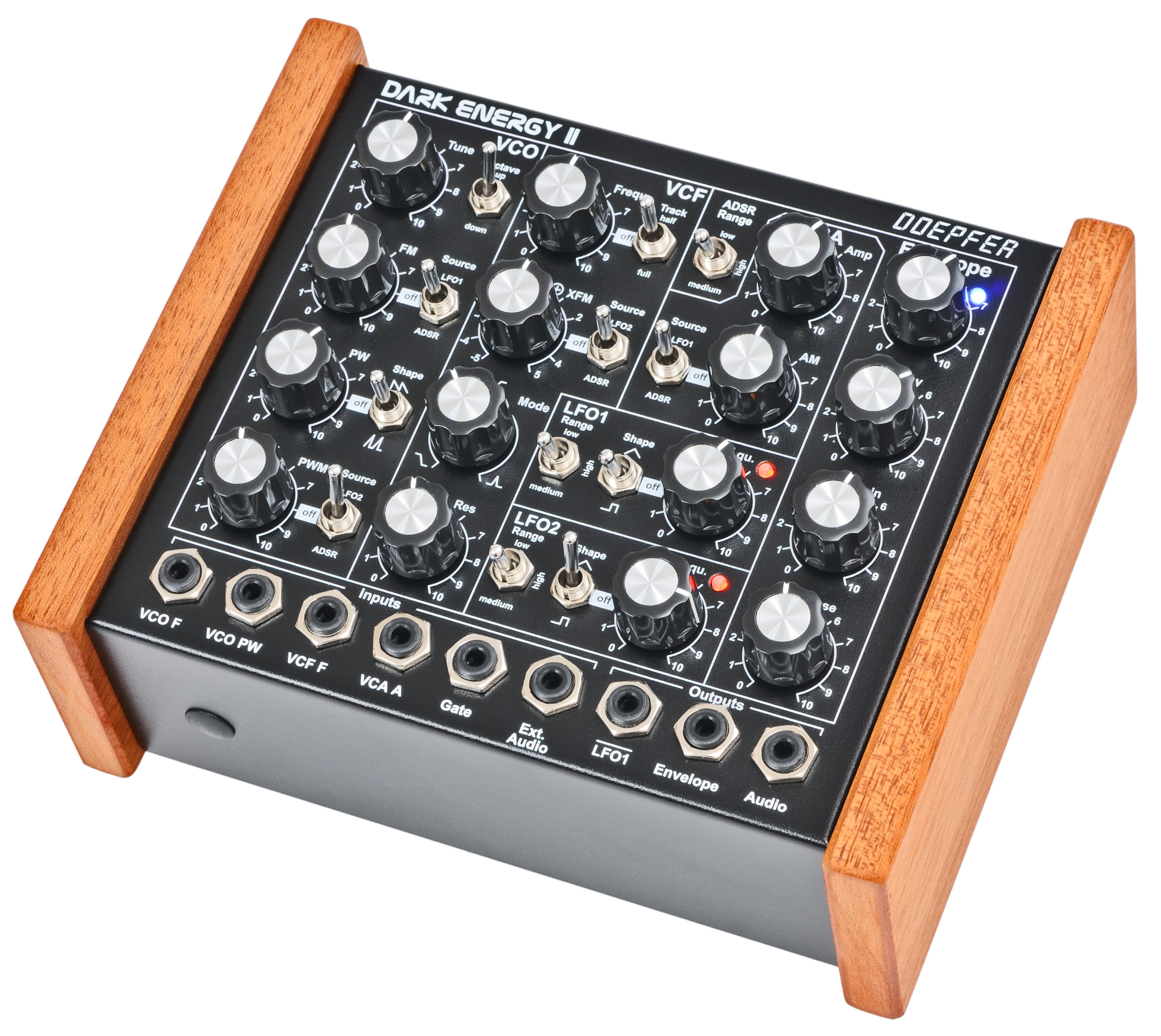
DARK ENERGY II
No longer
available !
replacement: Dark
Energy III
(click to enlarge)
Dark Energy II is a monophonic stand-alone synthesizer with USB and Midi interface. The sound generation and all modulation sources are 100% analog, only the USB/Midi interface contains digital components. Dark Energy is built into a rugged black metal case with wooden side plates. High quality potentiometers with metal shafts are used and each potentiometer - except the filter mode control - is fixed to the case (no wobbly shafts and knobs). The distance between the controls is a bit wider compared to A-100 modules and knobs with vintage look are used.
VCO
- Sawtooth based VCO core
- manual tune control (with an internal jumper the range can be set to ~ +/-1 half an octave or ~ +/-2.5 octaves)
- range switch -1 / 0 / +1 octave
- frequency range about 32 Hz/C0 (reference note and octave switch in position -1) to about 4.2 kHz/C8 (reference note plus 5 octaves and octave switch in position +1)
- FM (frequency modulation) control with modulation source switch (LFO1 / off / ADSR)
- manual pulsewidth control for rectangle waveform
- PWM control with modulation source switch (LFO2 / off / ADSR)
- waveform switch (sawtooth / off / clipped/inverted sawtooth)
- the sum of the waveform chosen by this switch and the rectangle is fed into the VCF (to turn the rectangle off the PW control has to be set fully CCW)
- external CV input for VCO frequency (1V/octave)
- external CV input for external PWM of the rectangle
- internal CV input for frequency (1V/octave) connected to the CV1 output of the built-in USB/Midi interface
- because of the pure analog circuit and the temperature control it may take up to 30 minutes until the VCO is in tune.
VCF
- 12dB multimode filter with lowpass, notch, highpass and bandpass
- mode control for continuous transition from lowpass via notch to highpass and along to bandpass
- manual frequency control
- tracking switch half - off - full (internally connected to the external frequency CV input of the VCO, i.e. the VCF tracks to the VCO if the switch is set to "half" or "full" position)
- exponential frequency modulation control (XFM) with modulation source switch (LFO2 / off / ADSR), the XFM control has polarizer function, i.e. the modulation source (LFO2 or ADSR) selected by the Source switch may affect the filter frequency in a positive (right half of the control range) or negative way (left half of the control range)
- manual resonance control (up to self oscillation)
- external audio input (this signal is added to the VCO signal)
- external CV input for filter frequency
- 1V/octave tracking for usage of the VCF as a sine wave oscillator over a few octaves (not as precise as the VCO and not temperature compensated, but much better than most of the other filters)
VCA
- manual amplitude control (initial gain)
- AM (amplitude modulation) control with modulation source switch (LFO1 / off / ADSR)
- external CV input for VCA amplitude
- exponential scale.
LFO1 and LFO2
- manual frequency control
- waveform switch (triangle / off / rectangle)
- range switch (low, audio, medium)
- LED display (dual green/red color for positive/negative share of the signal)
- the LFO1 signal is available as an additional socket (to use the LFO1 signal for external modules)
- an internal jumper can be used to select between the LFO1 signal or the inverted LFO1 signal
ADSR
- manual controls for Attack, Decay, Sustain, Release
- range switch (long, short, medium)
- blue LED display
- ADSR signal is available as an additional socket (to use the ADSR signal for external modules)
- External Gate input (normalled via switching contact of the socket to the Gate output of the built-in USB/Midi interface)
USB/Midi-Interface
- Midi channel and reference note are adjusted by means of a learn button and LED at the rear panel
- The interface generates the gate signal that controls the envelope generator and three analog control voltages: CV1 is used to control the pitch of the VCO, CV2 the VCF frequency (free assignable Midi controller) and CV3 is available as an additional socket at the rear panel (controlled by volume/velocity). It can be patched e.g. to the VCF control input to control the filter via velocity.
- CV voltage range 0... +5V (corresponds to 5 octaves)
- The threes CVs and the gate signal are also available at the rear panel as jack sockets
- cascading of several units via internal Midi Out/Midi In connection, because of shortage of space the unit has no Midi Out socket available this connection has to be established internally, for this the metal case has a hole on both sides so that the Midi Out/In connection can be made via this hole provided that both units are mounted to one another, the Midi Out has Midi Thru function with one exception: the signal does not include the Midi note messages that have been processed already, consequently polyphonic cascading (all daisy-chained Dark Energies on the same Midi channel) or monophonic cascading (different Midi channels) is possible, it's possible to connect only the first unit to USB and pass on the Midi data via the internal Midi link to other devices)
In/Outputs (all monophonic 3.5 mm jack sockets, except USB, Midi and power supply)
- front
panel:
- CV In VCO frequency (1V/oct)
- CV In VCO pulsewidth (about 5V range for full scale)
- CV In VCF frequency (~ 1V/oct)
- CV In VCA amplitude (0...+5V)
- Gate In (0/+5...12V)
- External Audio In (typ. 1Vss without distortion)
- inverted LFO1 Out (~ -2.5 ... +2.5V)
- Envelope Out (~ 0 ... +6V)
- Audio Out (line output, typ. 1Vss, monophonic)
- rear
panel:
- USB
- Midi In
- Learn button
- Gate Out (with LED for Gate display and learn function), 0/+5V
- CV1: controlled by Midi note messages, 1V/Oct, 0...+5V, internally connected to VCO CV input
- CV2: controlled by Midi pitch bend, ~ -2.5...+2.5V or ~ 0...+5V (can be selected by an internal jumper), no internal connection, the socket can be patched e.g. to the VCO or VCF CV input at the front panel
- CV3: controlled by Midi velocity, 0...+5V, no internal connection, the socket can be patched e.g. to the VCF input at the front panel
- CV4: controlled by Midi control change messages, free assignale controller in learn mode, no internal connection, the socket can be patched e.g. to the VCF or VCO pulsewidht input at the front panel
- the CV4 socket can be used also as audio output, the function of the socket can be selected by an internal jumper, factory setting is CV4, when changed to audio output no cable at the front panel is required (unless one wants to patch something), in this case CV4 is not available
- power supply (12...15V AC, min. 800mA)
- internal
connections
- Midi out (pin header with 2 pins for internal routing of the Midi signal to another Dark Energy)
- Midi in (pin header with 2 pins for internal routing of the Midi signal from another Dark Energy)
- By means of this internal connections several Dark Energy devices can be daisy-chained. Only the first device has to be connected to the Midi or USB transmitter. For this purpose the side plates of the metal case are equipped with holes that allow the internal connection of 2 or more Dark Energy devices. For this the metal cases have to be mounted directly to each other without wooden sideplate between the units. If a wooden side plate is desired between the devices one has to drill a hole to enable the internal connection.
- Several devices can be daisy-chained multiple monophonic (i.e. each Dark Energy received at a different Midi channel) or polyphonic (i.e. all devices are adjusted to the same Midi channel). For polyphonic applications a special stack mode is available. In this mode the device in question does not transmit note messages at the Midi output that are used to generate the tone in the device. Only "unused" note messages are transmitted.
Additional remarks and specs:
- As the LFO frequencies can go up to moderate audio range (~ 5kHz) even audio FM effects of VCO (pitch and pulsewidth), VCF and ADSR are possible !
- If the VCO is turned off (waveform switch = center position, pulsewidth control = fully CCW) and the VCF resonance is set to maximum the module can be used as a sine oscillator. The sine can be modulated in a linear manner from the triangle wave of the VCO and by LFO2 in an exponential manner at the same time !
- from the factory the socket labelled "LFO1" outputs the inverted LFO1 signal. But as the module has several internal pin headers available even another signal may appear at this socket by changing the internal module patch. These six pin headers are available: LFO1 output, LFO2 output, ADSR output, inverter input, inverter output, output socket. The internal default patch is LFO1 -> inverter input, inverter output -> output socket (i.e. socket = inverted LFO1). But even another signal can be patched to this socket (e.g. inverted ADSR, non-inverted LFO1, inverted or non-inverted LFO2). It is also possible to add a blind panel next to the A-111-5 with a couple of sockets that are connected to the corresponding pins of the A-111-5 pc board. The inputs and outputs of the VCO, VCF and VCA are not available as pin headers because the VCO, VCF and VCA are internally connected in the circuit which is used in this module.
- The attenuators for VCO FM and VCF FM are exponential types to enable a better resolution of the modulation depth in the lower range
- Weight: about 1.2 kg (without power supply)
- Distance between the knobs (center - center): ~ 25 mm, diameter of the knobs: ~ 16 mm
- The metal case is made of 1 mm steel, black coated with white printing
- Overall dimensions: about 185 x 145 x 75 mm
- Dimension of the metal case only (without side plates and knobs): about 145 x 135 x 55
- Side plates dimensions: about 145 x 65 x 12.5 mm
- The wooden side plates can be removed if desired. They are mounted by means of two screws to the metal box. The holes in the metal box can be used also to mount several devices together (e.g. with common wooden side plates on both ends).
- The device can be positioned horizontal (desk top) or vertical
- These parts are included: power supply (12 AC/min. 800mA) for 230V mains voltage with European mains plug, one adapter cable 3.5 mm - 6.3 mm /1/4" jack plug (1.5 m length), one USB cable (type A-B, 2 m length) and two A-100 patch cables (50 cm length)
- Powering the device via USB is not possible, because the analog circuits require a dual voltage (+/-12V).
- A lot of additional functions are available as internal pin headers (e.g. VCO outputs, linear FM input for VCO, hard SYNC input for VCO, VCF outputs, LFO outputs, LFO connections for optional reset/direction features, ADSR outout, inverter input and output). Important note: warranty is void if a defect caused by wrong wiring of these additional pin headers is discovered !
For detailed information the user's manual (Dark_Energy_II_Manual.pdf) and a document with additional technical information (e.g. for modifications, adjustment) is available (Dark_Energy_II_technical_information.pdf). The glide option contains a pre-wired glide potentiometer with two nuts and a Dark Energy style rotary knob.
In addition there are some answers on our FAQ pages: Dark Energy FAQ
Remark: The supply connector at the rear panel of the first series of Dark Energy II is labelled "15V AC/400mA". That's wrong ! The correct power supply is 12V AC / min. 800 mA (i.a. 800 mA or more). The power supplies delivered with the Dark Energy II are the right ones !
Once again the differences between Dark Energy I and II as summary:
-
12dB multimode filter with lowpass, notch, highpass and bandpass (instead of 24dB lowpass of Dark Energy I)
-
the previous LM control of the filter becomes the filter type control Mode (continuous crossfade lowpass - notch - highpass - bandpass)
-
the modulation level control of the filter "XFM" has so-called "polarizer" function. The modulation source (LFO2 or ADSR) selected by the Source switch may affect the filter frequency in a positive (right half of the control range) or negative way (left half of the control range)
-
the waveform switch is used to select between saw and clipped, inverted saw (in the center position the saw is off)
-
the basic waveform of the VCO is saw (not triangle like the Dark Energy I).
-
the VCA has a exponential scale (not the combined linear/exponential scale of Dark Energy I)
-
because of the pure analog circuit and the temperature control it may take up to 20-30 minutes until the VCO is in tune.
-
The sound of the Dark Energy II differs clearly from the Dark Energy I (mainly because of the completely different filter type). If you already own a Dark Energy I the Dark Energy II can be used as an expansion. But you will not be able to copy sounds of the Dark Energy I with the Dark Energy II (and vice versa) !
-
For users with electronic knowledge the Dark Energy II offers much more internal expansion features than the Dark Energy I. For example terminals (pin headers) for these features are available: VCO Hard Sync, linear VCO FM, rectangle and sawtoooth output of the VCO, lowpass/bandpass/highpass output of the VC, Reset/Sync/Direction for each LFO, rectangle and triangle output for each LFO. In addition an improved version of the glide option is is the planning stage that allows to turn on/off the glide function via Midi control change messages.
- APP Sound: https://www.youtube.com/watch?v=Q1EJzvr0Itg
- Sonicstate: http://www.sonicstate.com/news/2012/03/24/messe12-doepfer-dark-energy-ii/ (English)
- Musikmachen / Keyboards: http://www.musikmachen.de/Messe-News/Musikmesse-2012/Doepfer-Dark-Energy-2 (German)
- Debug: http://de-bug.de/musiktechnik/archives/5784.html (German)
Prices:
Dark Energy II incl. power supply and cables (as mentioned above): Euro 449,00 Euro
Gide Option (kit): Euro 10,00