A-141-2 Voltage Controlled Envelope Generator VCADSR / VCLFO
|
|
 |
|
Standard Edition |
 |
|
Vintage Edition |
Das Modul A-141-2 ist der Nachfolger des abgekündigten VCADSR-Moduls A-141. Gegenüber dem A-141 sind eine Reihe von Verbesserungen und Erweiterungen hinzugekommen: gemeinsamer Steuereingang für alle 3 Zeiten, Range-Schalter, invertierter Ausgang, zusätzlicher im Pegel spannungssteuerbarer Ausgang, Digital-Ausgänge für End of Attack und End of Release (wird u.a. für den VCLFO-Modus benötigt).
Hier im Überblick die technischen Eingenschaften des Moduls A-141-2:
-
spannungsgesteuerter Hüllkurven-Generator vom ADSR-Typ
-
Manueller Regler und Steuerspannungseingang mit Polarizern für jeden der Parameter Attack (A), Decay (D), Sustain (S) und Release (R). Die Wirkung der externen Steuerspannung ist mit den Polarizern CVA, CVD, CVS und CVD einstellbar. Eine Spannungserhöhung an einem der Steuerspannungseingänge CVA, CVD oder CVR verlängert die betreffende Zeit, wenn der Regler im positiven Bereich steht (rechts von der Mittelstellung). Gleiches gilt für den Sustain-Pegel, wobei Sustain jedoch ein Spannungspegel ist (keine Zeit).
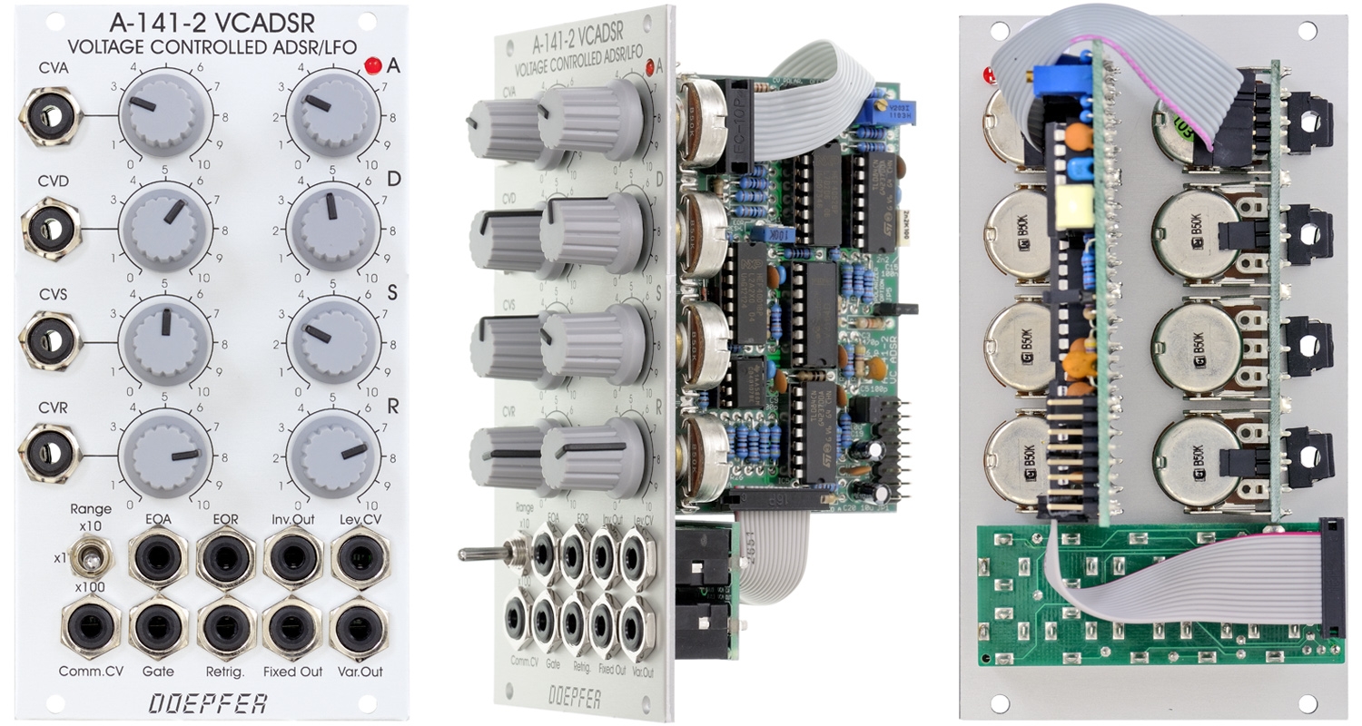
Hinweis: Das Foto der Standard-Edition zeigt noch die frühere Version mit Abschwächern für die CV-Eingänge (Skalen-Beschriftung 0-10). Das Modul wird aber schon seit längerem mit Polarizern ausgeliefert (Skalen-Beschriftung -5 - +5) -
Gemeinsamer Steuerspannungseingang (Comm.CV) für die drei Zeitparameter A, D und R. Hiermit können beispielsweise die Zeiten bei höheren Tönen automatisch verkürzt werden (wie beim Piano oder anderen Saiten-Instrumenten). Im VCLFO-Modus kann der Eingang für die Spannungssteuerung der Frequenz verwendet werden. Mit Hilfe eines Jumpers kann gewählt werden, ob dieser Steuereingang positiv (die Zeiten verlängern sich bei Spannungserhöhung, wie auch die A/D/R-Steuereingänge) oder negativ wirkt. In letzteren Fall verkürzen sich die Zeiten bei Spannungserhöhung, bzw. die Frequenz erhöht sich - wie bei einem VCO oder VCLFO. Um die Empfindlichkeit dieses Steuereingangs zu verändern, kann ein externer Abschwächer (z.B A-183-1) oder ein Abschwächer/Polarizer/Offset-Generator (z.B. A-183-2) verwendet werden.
-
3-facher-Zeitbereichsumschalter 10:1:100 mit den Zeitbereichen ca. 50us ... 6 s (Stellung "x1"), 500us ... 60s (Stellung "x10"), 5ms ... 10 min (Stellung "x100")
-
Gate-Eingang: ein Low/High-Übergang startet die Hüllkurve (Attack-Phase gefolgt von der Decay/Sustain-Phase), ein High/Low-Übergang beendet die Hüllkurve (Release-Phase), der High-Pegel der Gate-Spannung kann im Bereich +5...12V liegen
-
Retrigger-Eingang: hierbei wird die Hüllkurve solange der Gate-Eingang high ist mit jedem Trigger-Impuls an der Retrigger-Buchse neu gestartet, der High-Pegel des Retrigger-Signals kann im Bereich +5...12V liegen
-
normaler Hüllkurven-Ausgang (Fixed Out) mit festem Pegel (ca. 0...+7V)
-
invertierter Hüllkurven-Ausgang (Inv. Out) mit festem Pegel (ca. 0...-7V)
-
variabler Hüllkurven-Ausgang (Var.Out) mit Steuerspannungseingang (Lev.CV) zur Steuerung des Pegels mit einer externen Spannung (= zusätzlicher VCA am ADSR-Ausgang), z.B. für dynamischen Anwendungen, bei denen die Hüllkurven-Amplitude über eine Velocity-Spannung gesteuert wird, eine Steuerspannung von ca. +5V entspricht einem Verstärkungsfaktor 1 (d.h. Ausgangspegel ca. +7V wie der Fixed Out), bei Steuerspannungen über +5V kann der Pegel der Hüllkurve bis zur maximalen Aussteuerungsgrenze (knapp unter +12V) angehoben werden, danach beginnt das ADSR-Signal zu clippen. Der Level-CV-Eingang ist auf +5V normalisiert, d.h. wenn hier kein Patchkabel eingesteckt ist arbeitet der Var.Out-Ausgang als normaler, zweiter ADSR-Ausgang.
-
der variable Hüllkurven-Ausgang kann wahlweise als rein positiver Ausgang (eine Steuerspannung von ca. 0...+5V steuert den Pegel von Null bis ca. +7V) oder als Polarizer-Ausgang betrieben werden (einer Steuerspannung von 0V entspricht dann das invertierte Signal, +2,5V Steuerspannung entspricht 0V/kein Signal und +5V Steuerspannung entspricht dem vollen nicht-invertierten ADSR-Signal), die Betriebsart ist mit einer Steckbrücke zwischen normaler VCA-Funktion und Polarizer-Funktion umstellbar
-
End-of-Attack-Ausgang (EOA), dieses Signal schaltet auf high, wenn die Attack-Phase beendet ist und die Decay-Phase beginnt, das Signal schaltet zurück auf low beim Beginn der Release-Phase (wenn das Gate-Signal auf low schaltet)
-
End-of-Release-Ausgang (EOR), dieses Signal schaltet auf high, wenn das ADSR-Signal unter ca. +0,1V fällt (mit einem Trimmpoti ist der Schwellwert intern justierbar). Es schaltet zurück auf Low, sobald die Attack-Phase zu Ende ist. Dieses Signal kann insbesondere dazu verwendet werden, um das Modul als VCLFO zu betreiben. Hierzu wird der EOR-Ausgang mit dem Gate-Eingang verbunden. Das Modul arbeitet dann als Pseudo-VCLFO mit einstellbarer Anstiegszeit (Attack) und Abfall-Zeit (Release), der gemeinsame Steuereingang (Com.CV) kann dann dazu verwendet werden, die Frequenz über eine Spannung zu steuern. Die Kurvenformen für die Attack- und Release-Phase können wie im nächsten Absatz beschrieben verändert werden.
-
Mit Hilfe der getrennten Steuer-Eingänge für A, D und R kann auch die Kurvenform eines jeden Segments des ADSR-Signals verändert werden: Verbindet man den CVA-Steuereingang mit dem invertierten ADSR-Ausgang (Inv.Out) so kann man über den CVA-Regler die Kurvenform in der Attack-Phase ändern (Linksanschlag = normale exponentielle Kurvenform, Mittelstellung = annähern lineare Kurvenform, Rechtanschlag = negative exponentielle Kurvenform). Das gleiche gilt auch für die Kurvenformen in der Decay- und Release-Phase. Hier muss jedoch das nicht-invertierte ADSR-Signal dem betreffenden Steuereingang CVD bzw. CVR zugeführt werden.
-
Die Steuereingänge können über 2 interne Steckbrücken normalisiert werden (d.h. CVA-Buchse -> CVD-Buchse und CVD-Buchse -> CVR-Buchse). Damit können beispielsweise die Parameter Decay und Release mit der gleichen Steuerspannung gesteuert werden, ohne dass ein externes Multiple erforderlich ist.
-
Anzeige des Hüllkurven-Signals mit einer LED
-
Das Gate-Signal kann über eine Steckbrücke auch vom A-100-Bus geholt werden
Das folgende Dokument beschreibt die Funktion der Jumper: A141_2_Jumper.pdf
|
|
|
|
Standard Edition |
|
|
Vintage Edition |
Module A-141-2 is the successor of the obsolete
former VCADSR module A-141. Compared to the A-141 a lot
of improvements and expansions have been added:
common control voltage input for all time parameters (A/D/R), range switch for
three different time ranges, inverted ADSR output, additional output with
voltage controlled level (i.e. built in output VCA), digital outputs for
End of Attack (EOA) and End of Release (EOR), EOR is e.g. required for the VCLFO
mode.
Features overview:
-
voltage controlled envelope generator (ADSR type = Attack - Decay - Sustain - Release)
-
manual controls and control voltage inputs with polarizers for all parameters (A), Decay (D), Sustain (S) und Release (R). The effects of the control voltages can be adjusted by means of the assigned polarizer controls CVA, CVD, CVS and CVR. Increasing the control voltage at the inputs CVA, CVD or CVR increases the envelope time when the polarizer control is in the positive range (i.e. right from the center position). Same applies for the Sustain level. But Sustain is a voltage level rather than a time parameter.
Note: the picture of the standard edition still shows the earlier version with attenuators for the CV inputs (scale labelling 0 - 10). Since a few years the module is equipped with polarizers (scale labelling -5 - +5). -
common control voltage input (Comm.CV) for the three time parameters A, D and R. This input can be used e.g. to shorten all times for higher notes (like piano and many string instruments). In VCLFO mode this input can be used to control the frequency. By means of a jumper it can be chosen if an increasing control voltages increases the times A, D and R (same polarity as the CV inputs CVA, CVD and CVR) or if it lowers the times (and consequently increases the frequency in VCLFO mode, same polarity as the CV of a VCO). To adjust the sensitivity of this input an external attenuator (e.g. A-183-1) or attenuator/polarizer/offset generator (e.g. A-183-2) can be used.
-
three-position time range switch 10:1:100 with the approximate time ranges 50us ... 6 s (position "x1"), 500us ... 60s (position "x10"), 5ms ... 10 min (position "x100")
-
Gate input: a low/high transition starts the envelope (Attack phase followed by the Decay/Sustain phase), a high/low transisiton finishes the envelope (Release phase), the voltage level of the high state of the gate signal may range from +5V to +12V
-
Retrigger input: while the gate is high, a trigger pulse received at the retrigger socket will re-start the envelope from the beginning of its attack phase, the voltage level of the retrigger signal may range from +5V to +12V
-
normal envelope output (Fixed Out) with fixed level (about 0...+7V)
-
invertierted envelope output (Inv. Out) with fixed inverted level (about 0...-7V)
-
variable envelope output (Var.Out) control voltage input (Lev.CV) that controls the level of this output (nothing but an additional VCA behind the fixed output), e.g. for dynamic applications, where the envelope level is controlled by a velocity voltage, +5V control voltage corresponds to amplification +1 (i.e. the same +7V level as the fixed output), control voltages beyond +5V are possible and will increase the level until clipping occurs at about +12V. The Lev.CV input is normalled to +5V, i.e. if no cable is patched into Lev.CV the Var.Out can be used as a second ADSR with fixed level
-
two different modes of the variable envelope output can be selected by means of an internal jumper: normal VCA mode (as described above) or Polarizer mode (in this mode 0V CV corresponds to inverted envelope signal, about +2.5V correspond to no signal and +5V correspond to non-inverted envelope).
-
End-of-Attack output (EOA): this output turns high as soon as the Attack phase is finished and the Decay/Sustain phase begins
-
End-of-Release output (EOR): this output turns high as the fixed envelope signals falls below about +0.1 V (the threshold can be adjusted by means of a trimming potentiometer, the factory setting is +0.1V). The EOR signal turns low as soon as the Attack phase ends. This signal can be used to built a VCLFO with adjustable rising and falling time. For this EOR has to be patched to the Gate input. Then the module works as kind of a VCLFO. The common control voltage input can be used in addition to control the frequency by means of an external voltage (inverted scale as mentioned above), the shapes of the attack and release phase can be modified as described in the following paragraph
-
The control voltage inputs for A, D and R can be used also to change the shape of each segment. To change the shape of the Attack curve the inverted envelope output (Inv. Out) has to be patched to the CVA input. Then the CVA control is used to modify the shape of the Attack segment (CCW = usual exponential shape, about center position = linear shape, CW = inverse exponential shape). Same is valid for the shapes of Decay and Release also. But for this the non-inverted output (Fixed Out) has to be patched to the CV input in question (CVD or CVR or both).
-
The time control input sockets can be normalled by two internal jumpers (i.e. CVA socket -> CVD socket and CVD socket -> CVR socket). With this it's possible to control e.g. Decay and Relase with the same voltage without the need of an external multiple.
-
display of the envelope signal by means of an LED
-
The gate signal can be picked up from the internal gate signal of the A-100 bus by means of a jumper.
This document explains the functions of the jumpers: A141_2_Jumper.pdf
Tiefe/Depth: 70 mm (gemessen ab der Rückseite der Frontplatte / measured from the rear side of the front panel)
Strombedarf/Current: +40mA (+12V) / -30mA (-12V)
Standard Version : Euro 180.00
Vintage Edition : Euro 190.00
The price in US$ depends upon the exchange rate between Euro and US$ at the payment day.