A-143-2 Quad ADSR
click to enlarge |
|||||||||||||||||||||||||
 |
|||||||||||||||||||||||||
|
|||||||||||||||||||||||||
Die Modulserie A-143-x beinhaltet verschiedene
Mehrfach-Modulationsquellen. Das Modul A-143-2 ist ein vierfacher
Hüllkurven-Generator vom ADSR-Typ. Andere Module aus dieser Serie sind der
Komplexe Hüllkurven-Generator A-143-1 (Quad-AD) und
der Quad-LFO A-143-3.
Das Modul enthält 4 unabhängige ADSR-Hüllkurven-Generatoren. Jedes Sub-Modul
verfügt über die Regler Attack, Decay, Sustain und Release.
Mit dem 3-stufigen Range-Schalter ist der gewünschte Zeitbereich
wählbar (low - high - medium). Die einstellbaren Hüllkurven-Zeiten
reichen von mehreren Minuten bis einige Millisekunden. Zusätzlich ist jedes
Submodul mit 3 digitalen Ausgängen (high/low) ausgestattet: "End of Attack
(EOA)", "End of Decay (EOD)" und "End of Release
(EOR)". Bei Erreichen des jeweiligen Kriteriums (z.B. Ende der Decay-Phase)
schaltet der betreffende digitale Ausgang auf "high". Diese Ausgänge
können beispielsweise zum Kaskadieren mehrerer ADSRs verwendet werden. Sobald
das entsprechende Kriterium eintrifft (z.B. Ende der Decay-Phase) kann mit dem
betreffenden Ausgang ein weiterer ADSR getriggert werden. Auch automatisch
ablaufende Hüllkurven (Pseudo-LFOs) und "Quadratur-Hüllkurven" mit
zyklisch ablaufenden Modulationen mehrerer rückgekoppelter ADSRs sind hiermit
möglich. Um z.B. einen Pseudo-LFO zu erhalten, muss nur wird Ausgang EOD oder
der EOR auf den Gate-Eingang des betreffenden ADSRs gesteckt werden.
Zusätzlich zu dem bei allen Hüllkurven-Generatoren obligatorischen
Gate-Eingang, verfügt jedes der A-143-2-Submodule über einen
Retrigger-Eingang. Ein Retrigger-Impuls ändert die Hüllkurven-Richtung nach
oben, wenn bereits die Decay-Phase erreicht ist, wenn der Retrigger eintrifft.
Falls sich das Modul noch in der Attack-Phase befindet, hat der Retrigger-Impuls
keine Funktion. Bitte beachten Sie, dass dies ein anderes Verhalten als die
Retrigger-Eingänge der Module A-140 oder A-141.
Die Gate-Eingänge der unteren 3 Einheiten sind auf Gate-Eingang 1 normalisiert,
d.h. der Gate-Eingang 1 ist mit den Schaltkontakten der Gate-Buchsen der
Einheiten 2, 3 und 4 verbunden. Solange in die Gate-Eingänge 2, 3 und 4 keine
Patchkabel eingesteckt sind, werden diese Einheiten mit dem gleichen Gate-Signal
wie die Einheit 1 betrieben.
Der Verlauf jeder Hüllkurve wird mit einer LED optisch angezeigt. Die maximale
Hüllkurvenspannung (Umkehrpunkt Attack/Decay) liegt bei ca. +8V.
Falls Sie spannungsgesteuerte ADSR-Funktionen benötigen, so steht das Modul A-141 zur Verfügung.
Zur genaueren
Information steht die englischsprachige Bedienungsanleitung zur Verfügung:![]() A1432_man.pdf
A1432_man.pdf
In Ermangelung freier Modulnummern ist geplant, alle mehrfachen Modulationsquellen unter der Gruppennummer A-143 zusammenzufassen (A-143-1 Quad AD, A-143-2 Quad ADSR, A-143-3 Quad LFO usw.).
click to enlarge |
|
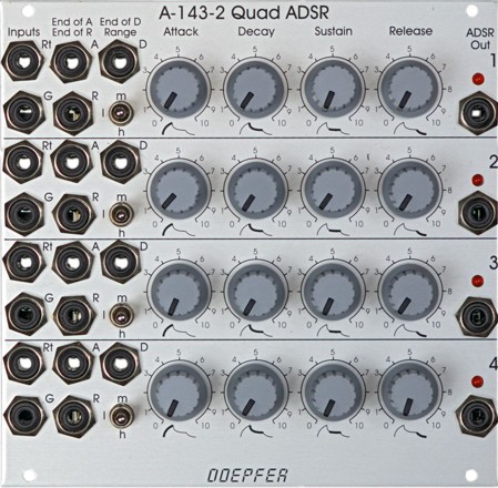
The A-143 series of modules contain multiple modulation sources. Module A-143-2 is a four-fold ADSR type envelope generator. Other modules of this series are the Complex Envelope Generator A-143-1 (Quad AD) and the Quad LFO A-143-3.
The module contains 4 independent ADSR-type envelope generators. Each sub-module has available the controls Attack, Decay, Sustain and Release. The three-position Range switch allows to select the desired time range (low - high - medium). The adjustable envelope time ranges from several minutes to some milliseconds. On top of this each sub-module is equipped with three digital outputs (high/low): "End of Attack (EOA)", "End of Decay (EOD)" and "End of Release (EOR)". As soon as the criterion is valid (e.g. end of decay state) the corresponding digital outputs turns to "high". These outputs can be used e.g. to daisy-chain several ADSR sub-modules. For this the digital output in question (EOA, EOD or EOR) has to be connected to the Gate input of the following ADSR. Even automatically running envelopes (pseudo LFOs) or so-called "quadrature envelopes" with cyclical modulations of several ring-shaped, daisy-chained ADSRs are possible. To obtain a pseudo LFO simply the EOD or EOR output has to be connected to the Gate input of the same ADSR.
In addition to the obligatory Gate (G)
input for envelope generators each sub-module has available a Retrigger
(Rt) input. The retrigger turns the
direction to "upward" if the envelope has already reached the decay
state while the retrigger pulse occurs. If the envelope is still in the attack
phase the retrigger input has no meaning. This a different behaviour from A-140
and A-141
!
The Gate inputs of the units 2, 3 and 4 are normalled to the Gate input of
unit 1, i.e. Gate input 1 is connected to the switching contacts of the Gate
input sockets 2, 3 and 4. Thus one Gate signal applied to Gate input 1 can be
used to trigger all four sub-modules simultaneously.
The envelope outputs are displayed with LEDs.
The maximal envelope voltage (Attack/Decay reversal point) is about +8V.
If voltage control of all parameters is required module A-141 is available.
A detailed description of the module can be found in the user's manual
![]() A1432_man.pdf
A1432_man.pdf
As we have not sufficient module numbers left, all multiple modulation sources will be probably collected in the A-143-x group (A-143-1 Quad AD, A-143-2 Quad ADSR, A-143-3 Quad LFO and so on).
| time ranges: | A | D/R | ||
| position range switch: |
min. | max. | min. | max. |
| l | ~ 0.3 ms | ~ 0.2 s | ~ 0.5 ms | ~ 0.5 s |
| m | ~ 5 ms | ~ 5 s | ~ 15 ms | ~ 10 s |
| h | ~ 30 ms | ~ 2 min | ~ 100 ms | ~ 5 min |
Tiefe/Depth: 50 mm (gemessen ab der Rückseite der Frontplatte / measured from the rear side of the front panel)
Strombedarf/Current: +70mA (+12V) / -50mA (-12V)
The price in US$ depends upon the exchange rate between Euro and US$ at the payment day.