A-192-2 Dual CV/Gate to Midi/USB Interface
|
|
 |
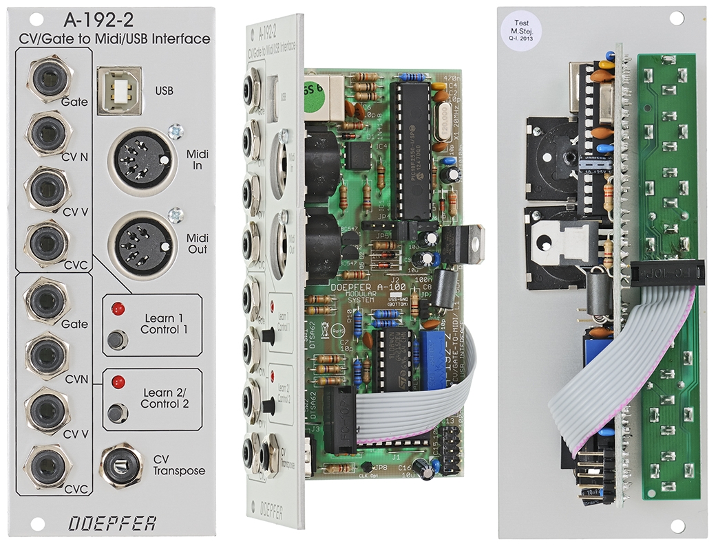
Module A-192-2 contains two independent CV/Gate-to-Midi/USB interfaces. For each of the two sub-units these inputs are available:
-
Gate Input (min. +5V)
-
CVN Input (defines the Midi note number), 1V/octave standard, range 0...+10V (i.e. 10 octaves)
-
CVV Input (defines the velocity value assigned to the Midi note message), can be used alternatively for Midi volume (CC#7), range 0...+5V
-
CVC Input (free assignable to any Midi control change number), range 0...+5V
For both sub-units a common CV Transpose input is available (1V/octave, range 0...+10V). The voltage applied to this input is added internally to CVN before the Midi note number is generated. It can be used e.g. to transpose two sequences simultaneously by one voltage.
How it works:
The LEDs of the sub-units are "on" as soon as the module is powered (kind
of power indicator lights). Whenever the rising edge of the Gate input is recognized a Midi note on
message is generated and the LED turns off. The note number corresponds to the sum of the voltages
applied to the CVN input and the common CV Transpose Input that is present at
the rising edge of the gate signal. As soon as the Gate input turns a Midi note
off
message is generated and the LED turns "on" (i.e. the LED works
reverse with regard to the Gate input signal).
Important
notes: The CV voltage has to be present at the rising edge of the gate
signal. It seems that for some sequencers on the market that's not true. If a
sequencer generates the CV after the rising edge of the gate the A-192-2 will
output apparently wrong Midi data because an "old" CV is taken to
generate the Midi data. But that's a problem of the sequencer, not the A-192-2.
To fix this problem the A-192-2 would have to "wait" a couple of
milliseconds (depending upon the delay between Gate and CV of the sequencer in
question) before the CV is measured. But this would degrade the timing because
then the Midi data are sent later then the rising edge of the gate signal.
Please clarify if you want to use the A-192-2 with a sequencer if the CV/gate
timing is correct (for the A-155 that applies of course),
i.e. please ask the manufacturer of the sequencer in question if the CV is
generated before the Gate and not the other way round.
Another problem may occur if already quantized control voltages are used
(actually the A-192-2 was designed for non-quantized control voltage like
"pure" analog sequencers without quantization). If the voltage steps
of the incoming quantozed CV are very close to the thresholds used by the
A-192-2 to distinguish between two Midi notes it may happen that now and then the
neighbouring midi note is chosen. The A-192-2 does not "know" anything
about the sequence structure but converts each CV independent from each other. Adding
or subtracting a small voltage to the CV coming from the quantized CV source
usually helps to solve the problem (e.g. by means of the upper channel of the precision
adder A-185-2) because then the voltage steps no longer
match to the thresholds of the A-192-2.
In Velocity mode
the voltage applied to the CVV input is used to define the velocity data of the
Midi note on message (in Volume mode a fixed velocity value 100 is
used). As soon as the falling edge of the Gate input is recognized the
corresponding Midi note off message is generated (i.e. with the same note
number as the preceding Midi note on message). The voltages at the CVN
and CV Transpose inputs during the falling edge of the Gate do not have an
effect on the note number of the note off message ! In any case the note
number of the preceding note on message is taken. Otherwise hanging Midi
notes would occur !
The CVV socket is normalled to +5V, i.e. as soon as the jack plug is removed
from the CVV socket the max. velocity or volume data (127) are generated.
Otherwise no audible sound would be generated (because of velocity or volume =
0).
The CVC voltage is permanently converted into the corresponding Midi control
change message, as well as the CVV voltage provided that the Volume mode
is chosen. The difference between Velocity mode and Volume mode is
the function of the voltage applied to CVV. In Velocity mode the voltage
CVV is used to define the velocity value of the corresponding Midi note on
message and is measured only during the rising edge of the Gate input. In Volume
mode the CVV voltage is permanently converted into Midi Volume messages
(Midi control change #7). The CVC socket is normalled to 0V, i.e. as soon as the
jack plug is removed from the CVC socket Midi control change data 0 are
generated.
Adjustment of the Conversion
Parameters
The conversion parameters for each unit are adjusted by means of the Learn
button in combination with incoming Midi data (e.g. generated by a Midi keyboard
connected to Midi In of the A-192-2). The learn mode is initiated by operating
the Learn button for about one second. While the unit is in learn mode
the corresponding LED is flashing. The next incoming Midi note on message
is used to set the Midi channel and note reference for the sub-unit in question.
The voltage currently applied to the CVN socket is assigned to the Midi note
number of the note message.
Example 1: 0V are applied to
CVN (or the CVN socket is left open) and a Midi note message with note number 36
on Midi channel 1 is sent while the upper sub-unit of the module is in learn
mode: then a CVN voltage of 0V corresponds to Midi note number 36 for the upper
sub-unit and the data are sent on Midi channel 1.
Example 2: +2.5V are applied to CVN and a Midi note message with note
number 47 on Midi channel 11 is sent while the lower sub-unit of the module is
in learn mode: then a CVN voltage of +2.5V corresponds to Midi note number 47
for the lower sub-unit and the data are sent on Midi channel 11.
When a Midi control change message is received while the unit is in learn mode the control change number of the Midi message is taken for CVC (except CC#0 and CC#32 as these are reserved for Midi program bank change). Program change messages are used in learn mode to select the Volume mode (program change #0) or Velocity mode (program change #1). Pay attention that the Midi channel of the incomung control change or program change messages has to correspond to the Midi channel that is assigned to the A-192-2 sub-unit in question.
In addition one can switch between the two modes without the need of a program change transmitter: for this one has to operate the learn button in question for several seconds. Then the LED starts to flash faster than in the learn mode and the other function for CVV (volume or velocity) is selected. But with this procedure one has no optical feedback which mode (volume or velocity) is selected. One simply is able to toggle between the two modes. But one can find out very simply which mode is selected because the module generates continuous Midi volume data only in the Volume mode. When a variable voltage applied to the CVV socket generates Midi volume data (without a Gate signal) the Volume mode is selected. Otherwise the Velocity mode is active.
The data generated by the module are transmitted simultaneously to Midi Out and USB. Two or more A-192-2 modules can be daisy-chained via Midi Out - Midi In. Incoming Midi data is merged to the Midi output - provided that the incoming data volume is not too high (because of the limited Midi Input buffer of the module). A Midi keyboard or a second A-192-2 are no problem but please do not try to merge a fully loaded 16 channel sequencer track.
The two LEDs also display the activity of the sub-units (i.e. if Midi data are generated by the unit in question) as described above in the chapter "How it works".
Factory settings:
-
Midi reference note for CVN = 0V: 36 (C)
-
Velocity mode (CVV generates velocity data)
-
Midi control change number assigned to CVC: #1 (modulation)
-
Sub-unit 1: Midi channel 1
-
Sub-unit 2: Midi channel 2
The factory setting can be restored by operating the learn button of the corresponding sub-unit during power on (i.e. the button has to be held down while the A-100 system is turned ON).
Typical applications:
-
Conversion of analog sequences into Midi/USB data (e.g. A-155)
-
Generating random Midi sequences (e.g. with CVN coming from A-118 or A-149-1, Gate e.g. from an LFO)
-
Generating Midi control change data from analog voltages
-
If bipolar or negative voltages have to be converted an offset generator is recommended (e.g. A-183-2). There is also an internal jumper available on the A-192-2 board that adds about +5V to the incoming control voltages CVN, CVV and CVC as soon as the jumper is installed. The pin header for the jumper is labelled "JP7" (next to the grey ferrit core).
Breite/Width: 10 TE / 10 HP / 50.5 mm
Tiefe/Depth: 55 mm
(gemessen ab der Rückseite der Frontplatte / measured from
the rear side of the front panel)
Strombedarf/Current: +70mA (+12V) / -20mA (-12V)
The price in US$ depends upon the exchange rate between Euro and US$ at the payment day.