A-188-2 Tapped BBD Module
nicht mehr lieferbar / no
longer available

|
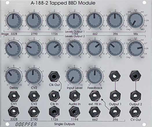
| Note: The labelling of the output sockets is wrong. The left pair of sockets is Output 2, the right pair is Output 1 |

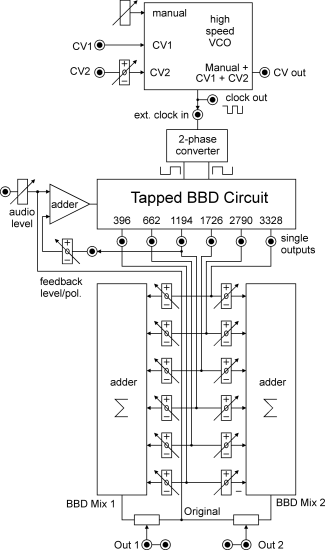
A-1882 module scheme
A-188-2 is another module that is based on a so-called Bucket Brigade Device (BBD). If you are not familiar with BBDs please refer to the A-188-1. There you can find some details about this special type of circuits.
The main difference between A-188-1 and A-188-2 is the type of BBD circuit that leads to completely different module principles and sounds. The A-188-1 uses different single BBD chips with one signal input and one signal output only. In contrast the A-188-2 uses as so-called tapped BBD that has available six outputs - the so-called taps after the BBD stages 396, 662, 1194, 1726, 2790 and 3328. In the A-188-2 we use this special BBD circuit (MN3011) to obtain these module features:
The module has available two separate mixing sub-units. For both mixers the levels and polarities of each BBD output can be adjusted to obtain two different mixtures of the BBD outputs. A new type of potentiometers with center detent and center terminal is used for the BBD mixing controls to have a better feel for the neutral position. Each mixer has a wet/dry control at its output that allows choosing between the pure input signal (original), the BBD mix or anything in between. The two outputs can be treated as stereo outputs but it is also possible to use one of the outputs for other applications (details in the next paragraph).
The
A-188-2 has a feedback section available that is very similar to the one in the A-188-1.
But as we now have 6 different BBD outputs available 6 different feedback types
are possible. The feedback input socket is normalled to the
"396" output (not to "1194" as shown in the scheme, the
front panel is correct). But by patching the feedback socket to any of the single
output sockets another BBD tap can be used for the feedback to obtain different
sounds. Even external feedback processing is possible (e.g. with a VCA for
voltage controlled feedback). The feedback control has polarizer function, i.e.
the neutral position is at the center. Left from the center the feedback signal
is subtracted from the input signal, right from the center it's added
(negative/positive feedback). Even for this potentiometer the new version with
center detent is used.
A special feedback can be obtained if one of the mix outputs is used for the feedback
function. In this case for each tap the positive or negative feedback share can
be adjusted. This leads to multiple peaks and/or notches in the frequency
response of the module.
For each tap of the BBD a separate output socket is available. These sockets can be used for changing the feedback loop - as mentioned above -, for voltage controlled mixing of the taps - e.g. with the voltage controlled mixer A-135 or other applications that require access to each single tap.
The A-188-2 uses the same high speed VCO (HSVCO) for the BBD clock as the A-188-1. The clock and consequently the delay time can be controlled manually (delay control) and by the two control voltage inputs CV1 and CV2. The sensitivity of CV1 is approximately 1V/oct. CV2 is equipped with a polarizer (a new type of potentiometers with center detent). The HSVCO has a clock output available that is normalled to the clock input socket. These sockets can be used to link different BBD modules and to run them with the same clock. But even other applications with frequency dividers (e.g. A-163) or PLL (e.g. A-196) are conceivable. A voltage composed of the manual delay control, CV1 and CV2 is available at the CV out socket, e.g. to control an external clock suppression filter as the A-188-2 is not equipped with such a filter (same as for the A-188-1).
Important note (especially for A-188-1 users): The A-188-1 uses single BBD circuits, which can be adjusted to minimize the clock noise as the outputs of the used BBD circuits are symmetrical (for details please refer to A1881_adjustment.pdf, trimming potentiometer P10). By way of contrast the BBD circuit used in the A-188-2 (MN3011) has six asymmetrical outputs that cannot be adjusted to minimize the clock noise. In addition the clock noise of the six outputs adds up. From there the clock noise of the A-188-2 is more intense than of the A-188-1. This is caused by the properties of the MN3011 but not a mistake of the module ! If you feel that the clock noise is too much you have the right to return the unused module within 14 days (i.e. the module has no scratches or prints, e.g. from srewing into the frame).
A
more detailed description of the module can be found in the user's manual
![]() A1882_man.pdf.
A1882_man.pdf.
Tiefe/Depth: 70 mm
Strombedarf/Current: +120mA (+12V) / -50mA (-12V)
nicht mehr lieferbar / no longer available
Because of the obsolete BBD circuit used in the A-188-2 (MN3011) the module cannot be manufactured anymore.