A-147-5 Quad VCLFO
| click to enlarge | click to enlarge |
|
|
|
|
Standard Edition |
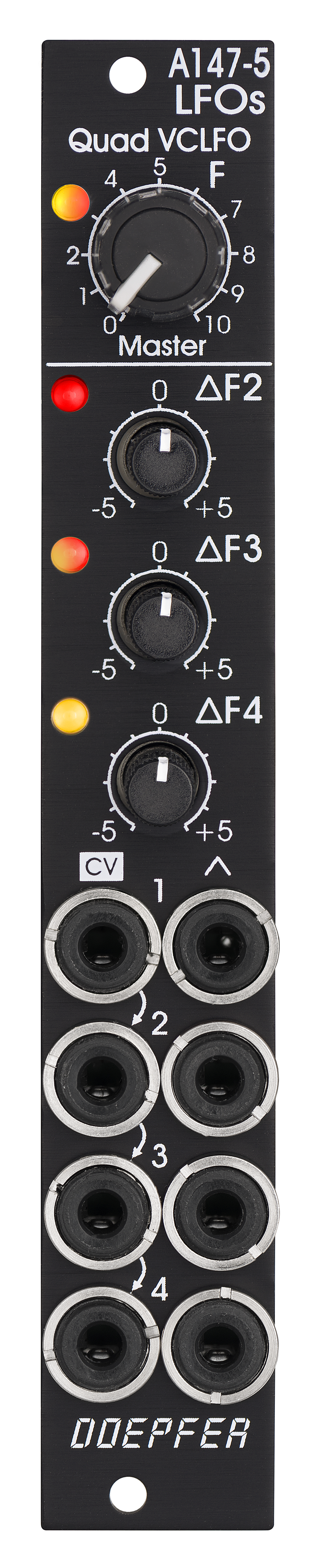
Vintage Edition |
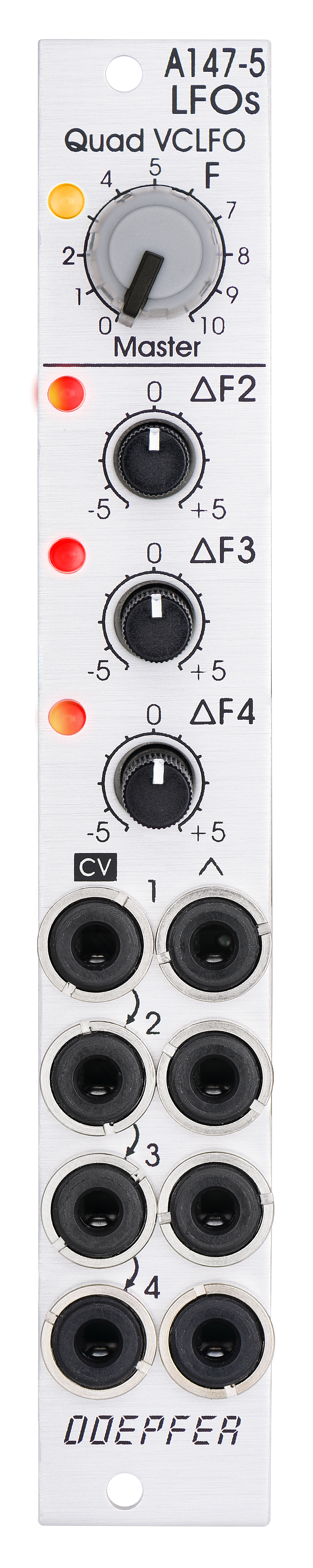
Das Modul verfügt über folgende Bedienelemente und Ein/Ausgänge:
-
Regler F: manuelle Einstellung der Frequenz für alle vier LFOs
-
Regler Delta F2, F3 und F4: manuelle Einstellung der Frequenzabweichung nach unten/oben für den betreffenden LFO
-
Buchsen CV 1...4: Frequenz-Steuerspannungs-Eingänge 1...4 (von oben nach unten normalisiert)
-
Buchsen mit Dreieck-Symbol 1...4: Dreieck-Ausgänge
-
LEDs: optische Anzeige der Dreieck-Ausgänge (rot = positive, gelb = negative Ausgangsspannung)
Anwendungsbeispiele:
-
Erzeugung von 4 Modulationssignalen, die relativ zueinander in der Frequenz einstellbar sind, aber zusätzlich über einen gemeinsamen Regler für die Frequenz aller Signale verfügen
-
Erzeugung von 4 Modulationssignalen für polyphone FM/PWM-Anwendungen: Hierzu werden die 4 CV-Eingänge mit den gleichen Steuerspannungen wie die zugehörigen VCOs gesteuert. Die Frequenzen der Modulationssignale folgen dann annähernd den Frequenzen der VCOs, wobei aber zusätzlich die Frequenzen aller LFOs (Regler F) und die Frequenz-Abweichungen der LFOs (Delta-Regler) eingestellt werden können. Für die simultane Steuerung der Modulations-Tiefen wird ein Quad-VCA vom Typ A-130-4 empfohlen.
-
Erzeugung komplexer Modulationen durch Aufsummieren der Ausgänge (z.B. mit einem Mixer A-138n / A-138i / A-138j)
Technische Hinweise:
-
Die Pegel der Dreieck-Ausgänge liegen bei ca. +/-5V (10Vss)
-
Die manuell einstellbare Frequenz reicht von ca. 0,025Hz (ca. 40 Sekunden) bis ca. 50 Hz, wenn sich die Delta-Regler der LFOs 2, 3 und 4 etwa in Mittelstellung befinden.
-
Die mit den Delta-Reglern einstellbaren Abweichungen liegen bei ca: +/-1:5. Beispiel: bei 1 Hz in Mittelstellung werden ca. 0,2 Hz bei Position -5 erreicht (1 Hz/5 = 0,2 Hz) und ca. 5 Hz bei Position +5 erreicht (1 Hz*5 = 5 Hz).
-
Die Bedienelemente und die Steuerspannungseingänge haben ein exponentielles Regelverhalten
-
Mit externen Steuerspannungen sind Frequenzen bis ca. 150 Hz möglich.
-
Die Kennlinie der CV-Eingänge beträgt grob 1V/Oktave (nicht justierbar)
-
Die CV-Eingänge sind von oben nach unten normalisiert. Wird nur an Buchse CV1 eine Steuerspannung angelegt, so steuert diese die Frequenz aller vier LFOs
-
Wird jeder CV-Eingang mit einer eigenen Steuerspannungsquelle verbunden, so wird jeder LFO unabhängig von den anderen gesteuert. Der CV-Eingang 1 wirkt dann nur auf LFO 1.
-
Intern sind 4 Anschlusspunkte für die Dreieck-Signale verfügbar, um die LFO-Signale intern mit anderen Modulen zu verbinden (z.B. mit dem A-130-4 und weiter zum A-111-4 für polyphone Modulationen)
-
Intern sind auch die Rechtecksignale der LFOs an 4 Anschlusspunkten verfügbar (ca. +/-10V bzw. 20Vss Pegel). Diese können z.B. mit Hilfe eines vom Anwender selbst gebauten Erweiterungs-Moduls über 1k-Schutzwiderstände auch auf Buchsen nach außen geführt werden. Falls geringere Pegel benötigt werden, können passive Abschwächer (Spannungsteiler) vorgesehen werden.
-
Intern steht auch ein (ungepuffertes) Dreieck-Summensignal an einem Anschlusspunkt zur Verfügung. Hierzu ist jeder der vier Dreieck-Ausgänge über einen 47k-Widerstand mit dem Summenausgang verbunden. Dieser Ausgang ist daher relativ hochohmig und sollte gepuffert werden, um Pegeländerungen bei unterschiedlicher Belastung zu vermeiden (z.B. mit einem A-180-3 oder A-180-4 oder A-183-3).
-
Durch Ändern der frequenzbestimmenden Kondensatoren können auch andere Frequenzbereiche gewählt werden (z.B. Quad-VCO als Cloud-VCO). Die Genauigkeit der Kennlinie der CV-Eingänge ist aber nicht für sauberes 1V/Oktave-Tracking ausreichend. Die 1V/Oktave-Kennlinien können nicht justiert werden und die Schaltungen sind nicht temperatur-kompensiert.
The module has these controls and in/outputs available:
-
Control F: manual control of the frequency for all four LFOs
-
Control Delta F2, F3 and F4: manual control of the frequency shift up/down for the LFO in question
-
Sockets CV 1...4: Frequency control voltage inputs (normalled from top to bottom)
-
Sockets with triangle symbol 1...4: triangle outputs
-
LEDs: visual displays of the triangle outputs (red = positive, yellow = negative output voltage)
Application examples:
-
Generation of four triangle modulation signals with a common frequency control for all LFOs and individual controls for the frequency deviation of each LFO, manually adjustable and controllable by external control voltages
-
Generation of modulation signals for polyphonic FM/PWM applications. For this the four CV inputs are connected to the same control voltages which are used to control the frequencies of the corresponding VCOs. That way each LFO follows the frequency of the associated VCO with the possibility to control the frequency of all VCOs (control F) and the frequency deviations (Delta F controls). For the simultaneous modulation depth control the Quad VCA module A-130-4 is recommended.
-
Generation of complex modulation signals by summing up the outputs (e.g. by means of a mixer module A-138n / A-138i / A-138j)
Technical notes:
-
The level of the triangle outputs is about +/-5V (10Vpp)
-
The manually adjustable frequency ranges from about 0.025 Hz (about 40 seconds) to about 50 Hz with the delta controls of LFOs 2, 3 and 4 about center position
-
The frequency deviations adjusted by the delta controls are about +/-1:5. Example: with 1 Hz in center position the frequency shift ranges from about 0.2 Hz in position -5 to about 5 Hz in position +5 (1 Hz/5 = 0.2 Hz, 1 Hz*5 = 5 Hz).
-
The manual frequency controls and the control voltage inputs have an exponential control behavior
-
With external control voltage the max. frequency is about 150 Hz, the minimum frequency
-
The scale of the CV inputs is roughly 1V/oct (not adjustable)
-
The CV inputs are normalled from top to bottom. Provided that only socket CV1 is patched CV1 controls the frequencies of all four LFOs.
-
When each CV input is patched to it's own control voltage each LFO is controlled individually by it's own CV. In this case CV1 controls only the frequency of LFO1.
-
Internally the four triangle signals are available at four terminals for internal connections to other modules (e.g. passing through A-130-4 to A-111-4 for polyphonic modulations).
-
Internally the four rectangle outputs are available at four terminals (typ level +/-10V or 20Vpp). If required they can be wired to four sockets of a DIY breakout module made by the user, 1k protection resistors are recommended to avoid short circuits. If lower levels are required passive attenuators (voltage dividers) may be used.
-
Internally is even an (unbuffered) triangle sum signal available. For this each of the four triangle outputs is simply connected to the sum output terminal via a 47k resistor. This output has high impedance and should be buffered or amplified to avoid level drop when the load changes (e.g. by means of an A-180-3 or A-180-4 or A-183-3).
-
By changing the values of the capacitors in the LFO circuits even other frequency ranges are possible (e.g. Quad VCO to form kind of a cloud VCO). Pay attention that the accuracy of the CV input scales is not sufficient for precise 1V/oct VCO applications. The 1V/Oct scales cannot be adjusted and the circuits are not temperature compensated.
Breite/Width: 4 TE / 4 HP / 20.0 mm
Tiefe/Depth: 45 mm (gemessen ab der Rückseite der Frontplatte / measured
from the rear side of the front panel)
Strombedarf/Current: +30 mA (+12V) / -30 mA
(-12V)
Standard Version : Euro 120.00
Vintage Edition : Euro 130.00
The price in US$ depends upon the exchange rate between Euro and US$ at the payment day.