A-100 Analog Modular System - Accessories and Spare Parts

The prices for the A-100 accessories you find in the price list in the section A-100 accessories or in the section spare parts.
As we are not an electronic distributor the prices for spare parts are high compared to the prices of an electronic distributor. So we suggest to order these parts only as spare parts and not for building other equipment. For the A-100 frames we use the 19 inch housing system of the German company Gie-Tec (www.gie-tec.de). Here you may get 19 inch housing accessories that fit to the A-100 system. But as we use the 19" standard the A-100 front panel may fit with frames from other manufacturers too. Doepfer only offers ready built A-100 frames, i.e. with built in power supply, bus boards, top/bottom/rear cover, mains inlet, power switch and fuse holder. Doepfer does does not offer single mechanical parts of the A-100 frames (like mounting rails).
Overview A-100 Accessories and Spare Parts
Order No Description

A-100Kxx


Rotary knobs

Standard knobs:

A-100KGR grey with black line
A-100KBK
black with white line
A-100KWH 
white with black line
A-100KRD 
red with white line
A-100KOR 
orange with white line
A-100KBR 
brown with white line
A-100KGN 
green with white line
A-100KBL 
blue with white line
A-100KMG
magenta with white line
A-100KYE 
yellow with black line

Vintage knobs:

A-100KV, same knob as used in the modules of the Vintage Edition (e.g. A-110-2), black body with 2 white dots and metal disk at the top side

Slim knobs:
(small, rubberized knobs,
11.5 mm diameter, used in the slim modules)

A-100KSB black with white line
A-100KSG
grey with black line
coming soon:

A-100KSR
red with white line
A-100KSY yellow with black line

The prices can be found in the price list in the section spare parts

A-100BUSV5 (old)


Running out - sale while stocks last !

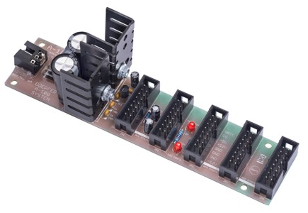
A-100BUS / Bus board
(old version 5 manufactured until end of 2019 with 14 unboxed bus connectors)


one assembled and tested bus board, e.g. for customers who want to built their own case and need a bus board for A-100 modules,  14 unboxed bus connectors (pin headers with 16 pins each), control LED for -12V, +12V and +5V 

until end of 2015: includes cables for connection of GND, -12V and +12V to the power supply (3 wires with flat connectors on both ends, length about 30cm, 0.75mm2 cross section)
since
end of 2015: includes cables for connection of GND, -12V, +12V and +5V to the power supply (4 wires with flat connectors on both ends, length about 30cm, 0.75mm2 cross section)

does not include mechanical parts for mounting (e.g. screws, spacers, nuts, washers) as the requirements for these parts depend upon the case (especially material and thickness of the back panel)
Dimensions: ~ 390 mm (lenght) x 43 mm (width) x 15 mm (height, without spacers and female connectors of the module bus cables)

The following dimensional drawing shows the positions of the mounting holes: A100_busboard_measures.pdf 

The prices can be found in the price list in the section A-100 accessories 

A-100BUSV6 (new)


A-100BUS / Bus board
(new version 6 manufactured from early in 2020 with 22 boxed bus connectors)


one assembled and tested bus board, e.g. for customers who want to built their own case and need a bus board for A-100 modules,  22 boxed bus connectors (boxed pin headers with 16 pins each),
control LED for -12V, +12V and +5V  

includes cables for connection of GND, -12V, +12V and +5V to the power supply (4 wires with flat connectors on both ends, length about 30cm, 0.75mm2 cross section)

does not include mechanical parts for mounting (e.g. screws, spacers, nuts, washers) as the requirements for these parts depend upon the case (especially material and thickness of the back panel)
Dimensions: ~ 391 mm (lenght) x 42 mm (width) x 20 mm (height, without spacers and female connectors of the module bus cables)

The following dimensional drawing shows the positions of the mounting holes: A100_busboard_measures.pdf 

The prices can be found in the price list in the section A-100 accessories 

Important technical note
In the new version of the A-100 bus board (labeled Version 6 / 2019) boxed pin headers are used which are equipped with a reverse protection (gap for the “nose” of the socket of the bus cable). When the bus cable coming from the module is connected to the boxed header in question the “nose” has to point to the right. The polarity of the cable is correct if the red wire of the bus cable then points to the bottom (to the continuous line labeled “RED WIRE” on the pc board). If this is not the case please do not connect the module to the bus board ! Otherwise both the module and the power supply may be damaged !  In that case please contact the manufacturer of the module and ask for a suitable bus cable with the correct polarity of the connector.

The bus cables of original A-100 modules manufactured by Doepfer are equipped with suitable bus cables since 2012. Only for older A-100 modules manufactured before 2012 it may happen that the polarity of the 16 pin female connector of the bus cable is wrong ("nose" points to the left when red wire points to the bottom). This is because in the past unboxed pin headers were used and the position of the “nose” did not matter. In such a case please contact Doepfer or one of their dealers and order a new suitable bus cable.

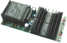
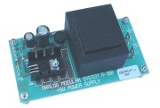
A-100NT12


A-100NT12 / A-100 Power supply I
assembled and tested power supply
Output voltages / currents: +12V DC/ 650mA, -12V DC/650mA
Input voltage: 230 V ACor 115V AC,  please specify 230V or 115V version
Input power: 25 Watt (full load)
does not include
cables, mains inlet, power switch, fuse and mounting material (screws, spacers, nuts, washers).

Suitable for qualified personnel only because of electrical safety (dangerous mains voltage 115V / 230V)

No longer available (used in older A-100 systems before 2004)

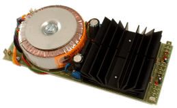
A-100PSU2


Running out - sale while stocks last !

A-100PSU2 / A-100 Power supply II
assembled and tested power supply with ring core transformer
Output voltages/currents: +12V DC/1200mA, -12V DC/1200mA
Input voltage: 230V AC or 115V AC, please specify 230V or 115V version
Input power: 45 Watt (full load)
does not include cables, mains inlet, power switch, fuse and mounting material (screws, spacers, nuts, washers)
up to four bus boards can be connected to the A-100PSU2, provided that the total current does not exceed 1200 mA

Dimensions: ~ 190 mm (lenght) x 80 mm (width) x 50 mm (height)
Weight: ~ 1kg
Ex factory the supply is equipped with four 10 mm long M3 distance bolts. Suitable screws have to be added by the customer because the required length depends upon the thickness of the baseplate.

Suitable for qualified personnel only because of electrical safety (dangerous mains voltage 115V / 230V). Only for qualified personnel these notes are available.

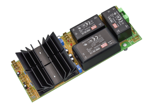
A-100PSU3


A-100PSU3 / A-100 power supply 3
assembled and tested power supply
Output
voltages/currents: +12V / 2000mA, -12V / 1200mA, +5V/2000mA (max. 4000mA when the 2A fuse is replaced by 4A)
Input voltage: 100...240V AC (wide range mains input) 
Input power: 75 Watt (full load)
does not include cables, mains inlet, power switch, fuse and mounting material (screws, spacers, nuts, washers)
up to four bus boards can be connected to the A-100PSU3, provided that the total currents are not exceeded

Dimensions: ~ 200 mm (lenght) x 80 mm (width) x 40 mm (height)
Weight: ~ 420 g
Ex factory the supply is equipped with four 10 mm long M3 distance bolts. Suitable screws have to be added by the customer because the required length depends upon the thickness of the baseplate.
For the connections to mains and bus board(s) the pc board is equipped with 6.35 mm male blade terminals. For the wiring of the board suitable 6.35 mm crimp female terminals have to be used.

The following dimensional drawing shows the positions of the mounting holes: A100_PSU3_measures.pdf

Suitable for qualified personnel only because of electrical safety (dangerous mains voltage 115V / 230V).  Only for qualified personnel these notes are available.

The price can be found in the price list in the section A-100 accessories 

General technical notes A-100PSU3

Internally the A-100PSU3 uses a +/-15V switching supply (wide range input 100...240V for mains voltage) followed by the classical linear regulation circuit of the A-100PSU2 that generates the required +12V and -12V. Only the +5V is a pure switching supply without linear regulation. We discovered that a pure 12V switching supply was not good enough for the modular system (especially the generated noise and the load regulation was not satisfying for all 12V switching supplies we tried). That's why we added the well-tried linear 12V regulation of the A-100PSU2 to the 15V switching supply. As the current for +12V and -12V is different the currents for +12V and -12V are specified separately for all modules.
Each of the three voltages (+12V, -12V, +5V) has it's own switching supply. Therefore the three voltages appear not exactly at the same time after power on because each switching supply has it's own power-on cycle. The delay time after power on is in the range 1 - 1.5 sec, the rise time in the range 20-30ms. It turned out that this may cause problems for digital modules manufactured by other manufactueres (probably the reset does not work as expected). For A-100 modules that's not a problem and probably as well not for pure analog modules from other manufacturers.

Technical note concerning the +5V fuse of  A-100PSU3

The +5V of the A-100PSU3 are equipped with a separate (hidden) fuse. The fuse is located on the pc board of the A-100PSU3 next to the +5V terminals. To reach the fuse it may be necessary to remove the power supply cover (2 screws). It's essential that the mains cable is disconnected before the cover is removed ! It's not sufficient to operate the mains switch only ! From the factory the A-100PSU3 is equipped with a 2A fuse (F/fast). If required the value can be increased up to max. 4A. But this is recommended only if really a higher current than 2A is required.

Notes for replacing A-100PSU2 by A-100PSU3

An existing power supply (A-100NT12 or A-100PSU2) can be replaced easily by the new A-100PSU3 because the A-100PSU3 has nearly the same dimensions and the four mounting bolts are at the same positions. No soldering is required because removable flat connectors are used for all connections. Nevertheless the replacement or installation has to be carried out by qualified personnel only because the correct wiring of the mains connection is essential. And it's essential that all parts that conduct mains voltage (cables, pc board, electronic parts on the pc board) are mechanically protected against any contact with the human body (touch-proof, e.g. by using a cover for the power supply). Otherwise there is Danger to Life ! Existing bus boards can be used. There is no need to replace the bus boards. Only if the +5V supply is required one has to add the cable(s) that connects the +5V terminal of the bus board(s) to the corresponding terminals of the A-100PSU3.

A-100PCS

A-100PCS power supply protection cover standard version (for one A-100PSU2/PSU3, used in all A-100 cases except the monster cases, A-100LC1, A-100LC3 and A-100MC)
The price can be found in t
he price list in the section A-100 accessories 

A-100PCM

A-100PCM power supply protection cover monster version (for 2 x A-100PSU2/PSU3, used in the monster cases)
The price can be found in the price list in the section A-100 accessories 

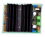
A-100DIY PSU


A-100 DIY PSU / Power Supply from the A-100 DIY Kit #1
assembled and tested power supply
Output: +12V DC/1200mA, -12V DC/1200mA
Input: 15V AC/2500mA (via external, capsulated transformer, please specify 230V or 115V version for the transformer)
available with or without external transformer (output 15V AC/2500 mA)
does not include
cables, power switch or mounting material (screws, spacers, nuts, washers)
up to four bus boards can be connected to the DIY kit supply, provided that the total currents are not exceeded

Dimensions: ~ 110 mm (lenght) x 80 mm (width) x 50 mm (height)
Weight: ~ 200 g (without ext. transformer), ~ 1100g (incl. ext. transformer), ~ 900g (ext. transformer only)
Ex factory the supply is equipped with four 10 mm long M3 distance bolts. Suitable screws have to be added by the customer because the required length depends upon the thickness of the baseplate.

The price can be found in the price list in the section A-100 accessories 

A-100NT5


A-100NT5 / 5V Power supply
assembled and tested additional power supply +5 V@ 500 mA, the installation of the 5V power supply has to be carried out by qualified personnel only who is familiar with the electrical safety rules! Available only for 230V mains voltage.

Suitable for qualified personnel only because of electrical safety (dangerous mains voltage 115V / 230V)

No longer available

Alternatively one of the power supplies of the German Sonderliste (special list) can be used to generate +5V. For currents less than 100 mA the 5V low cost adapter described below should be used.

A-100AD5


A-100AD5 / +5V Low-Cost Adapter
+5V@100 mA plug-in module
This module can be plugged into a free socket on the bus board for older A-100 modules which require +5V (e.g. A-113, A-190) or for modules from other manufacturers. The current is taken from the 12V supply !
Required only if +5V are needed and an older power supply (A-100NT12 or A-100PSU2) or the A-100 DIY supply is used.

Important technical note: Do not install the A-100AD5 when the A-100PSU3 is used ! This may damage the A-100PSU3 and/or the A-100AD5 !

No longer available

Alternatively one of the power supplies of the German Sonderliste (special list) can be used to generate +5V. For currents less than 100 mA the 5V low cost adapter described below should be used.

A-100SSB


version 1.1

A-100SSB/ A-100 Small Supply/Bus Board

ready built and tested unit, contains a small power supply and a short bus board
output:
+12V/380mA, -12V/380mA (+5V/100mA, the +5V current is taken from the +12V line !)
input: 100-240V AC/50.60Hz (wide range mains input via IEC inlet)

bus board:

  • version 1.1 (until about September 2019):
    8 nonpolarized bus connectors (unboxed pin headers), one common pc board for power supply and bus board,  outputs: +12V/380mA, -12V/380mA (+5V/100mA, the +5V current is taken from the +12V line !)

    no longer available
  • version 1.2 (from about September 2019):
    12 polarized bus connectors (boxed pin headers),
    one common pc board for power supply and bus board, outputs: +12V/380mA, -12V/380mA (+5V/100mA, the +5V current is taken from the +12V line !)
    Running out - sale while stocks last !
  • version 2 (from about May 2021):
    12 polarized bus connectors (boxed pin headers), two separate pc boards for power supply and bus board,
    outputs: +12V/340mA, -12V/340mA (+5V/100mA, the +5V current is taken from the +12V line !), precise and adjjustable output voltages, suitable also for VCOs

comes without mains cable and without mounting material (e.g. screws, spacers, nuts, washers) as the requirements for these parts depend upon the country (mains connector type) and the case (especially material and thickness of the case material)
Dimensions: ~ 270 mm (length) x 55 mm (width) x 35 mm (height)
mechanical and electrical skills are required to install and run the A-100SSB !

It's essential to pay attention to the safety notes mentioned in the user's manual:

The price can be found in the price list in the section A-100 accessories 


version 1.2

(picture coming soon)

version 2


A-100MNT/MBP


A-100 Miniature Power supply and bus bord (A-100MNT / A-100MBP)

Different versions of the A-100 miniature power supply are in circulation. We will mention all versions at this point but only the latest version 4 is available. All versions are ready built and tested pc boards and include a small power supply with an integrated bus board with four bus connectors. The main application if the miniature power supply is the power supply for one or a few modules only (up to four/five). The miniature power supply is also used in the miniatur case A-100MC.

  • Version 1.0 (recognizable by the small blank heat sinks as shown in the left picture, no longer available): +12V/100, -12V/100mA, +5V/50mA, requires a 9VAC adapter (i.e. 9V AC not DC), min. 300mA
  • Version 1.1 (same as version 1.0, but with larger, black heat sinks, no longer available): +12V/200mA, -12V/200mA, +5V/50mA, requires a 9VAC adapter (i.e. 9V AC not DC), min. 500mA
  • Version 2 and 3: +12V/200mA, -12V/200mA, +5V/50mA, requires a 12-15VAC adapter (i.e. 12-15V AC not DC), min. 500mA
  • Version 4: five boxed pin headers (instead of four unboxed pin headers of the former versions, +12V/200mA, -12V/200mA, +5V/50mA, requires a 12-15VAC adapter (i.e. 12-15V AC not DC), min. 500mA

Technical notes:

  • devices manufactured until about end of 2016 (versions 1.0 and 1.1) require an external transformer (AC/AC adapter) with 9V AC voltage output and are named A-100MNT. Running the old version with the external supply of the new version (12-15V AC) will damage the built-in power supply !
  • devices manufactured from about 2017 (version 2) requires an external transformer (AC/AC adapter) with 12-15V AC voltage output and are named A-100MBP (Miniature Bus/Power supply).
    • These units are either marked by a label with the words "12-15AV/>400mA". The label is located on the pc board of the power supply.
    • or the pc board is equipped with an imprint "A-100MBP Miniatur Bus/Power Supply" and "12-15V/>400mA
  • If there is no such label or imprint it's version 1.0 or 1.1 and the above mentioned 9V AC supply is required.
  • When the +5V supply is used up to 50mA are available. But the +5V current is taken from the +12V line and is missing for +12V (when e.g. 50mA are taken from +5V only 150mA remain for +12V)
  • external power supplies with DC output (instead of AC) are not suitable ! In this case only the positive or negative supply voltage will be present (depending upon the polarity of the DC supply).

Available with or without AC/AC adapter (only version for 230V mains voltage and European mains connector available)

Comes without mounting material (e.g. screws, spacers, nuts, washers) as the requirements for these parts depend upon the case (especially material and thickness of the case material)

Dimensions: ~ 142 mm (lenght) x 32 mm (width) x 50 mm (height)

The A-100MNT/MBP manuals are part of the A-100MC manuals:

The price can be found in the price list in the section A-100 accessories 

A-100B1
A-100
B1.5
A-100
B2/B2V
A-100
B4/B4V
A-100
B8/B8V
A-100B42/B42V

Blind front panels
(standard version, made of 2 mm silver-grey anodized aluminium)
no picture available no picture available
A-100B1
1 HP / 5 mm
(only required if modules with odd-numbered HP width from other manufacturers have to be combined with A-100 modules/frames, e.g. Harvestman)
A-100B1.5
1.5 HP / 7,5 mm
(only required to compensate gaps if modules from other manufacturers with different positions of the mounting holes - e.g. Analogue Systems - have to be combined with A-100 modules/frames)
A-100B2
2 HP / 10 mm
A-100B4
4 HP / 20 mm
A-100B8
8 HP / 41 mm
A-100B42
42 HP / 213 mm

Blind front panels
(vintage version, made of 2 mm black anodized aluminium)
no picture available no picture available no picture available no picture available
A-100B1V
not available
A-100B1.5V
not available
A-100B2V
2 HP / 10 mm
A-100B4V
4 HP / 20 mm
A-100B8V
8 HP / 41 mm
A-100B42V
42 HP / 213 mm
The prices can be found in the price list in the section A-100 accessories 

A-100B84

Blind back panel

Dimensions: about 128.5 x 436 x 2 mm

Remark #1: As the 5V power supply (A-100NT5) is no longer available the back panel is no longer equipped with the four holes for the 5V power supply shown in the left picture.
Remark #2: The back panel cannot be used as a 84 HP blind panel at the front side of the A-100 frame. The panel is a bit longer than 84 HP (= 426.7 mm) to cover the rear side of the A-100G6 metal frame completely. For this purpose two 42 HP blind panels have to be used (see above).

The price can be found in the price list in the section A-100 accessories 

A-100B84P


the picture still shows version 1 of the back panel

Back panel for power supply mounting (A-100NT12 / A-100PSU2 / A-100PSU3)

3U/84HP with mounting holes for 12V power supply (suitable for A-100NT12, A-100PSU2 and  A-100PSU3 ), mains inlet with power switch, fuse holder and wires to connect the power supply, without mains cable, without additional mounting material, made of 2 mm anodized aluminium, the panel is equipped with a universal label which has to be marked by the user corresponding to the mains voltage and installed power supply (mains voltage 115V or 230V for A-100NT12/A-100PSU2, 110...240V for A-100PSU3, and suitable fuse value).

Dimensions: about 128.5 x 436 x 2 mm

Version 0: mains inlet with built-in filter and separate mains switch (used until about 1996)  no longer available
Version 1: snap-in version of the mains inlet, without power supply cover  no longer available

Version 2: screwed version of the mains inlet, with additional power supply cover

The back panel is a bit longer than 84 HP to cover the rear side of the A-100G6 frame completely.

The price can be found in the price list in the section A-100 accessories 

Suitable for qualified personnel only because of electrical safety (dangerous mains voltage 115V / 230V).  Only for qualified personnel these notes are available.

A-100C15
A-100C30
A-100C50
A-100C50A
A-100
C80
A-100C120
A-100C200


Patch cords
available in different length, with 2 mono plugs 3.5 mm
A-100C15: 15 cm (yellow) A-100C30: 30 cm (black)

A-100C50: 50 cm (grey)

A-100C50A: 50 cm
with angled plug on one side
(orange)
A-100C80: 80 cm (red) A-100C120: 120 cm (blue) A-100C200: 2m (green)

A-100C30T: 30 cm
transparent
No longer available

A-100C50T: 50 cm
transparent

A-100C80T: 80 cm
transparent
Available only in these lengths and colors.

We also offer a black monophonic adapter cable from 1/4" to 3.5 mm with 1.5 m or 3m length:


The prices can be found in the price list in the section A-100 accessories 

A-100BM10
A-100BM16
A-100BM10: connection cable between module and bus (10-to-16 pin) 20cm length
A-100BM16: connection cable between module and bus (16-to-16 pin) 20cm length

The prices can be found in the price list in the section A-100 accessories 

A-100BC

CV/Gate bus connection cable
required if the CV and/or gate signals of two bus boards have to be connected. For this the CV or gate corresponding connection jumper in the middle of the bus board is removed and replaced by the connector of the A-100BC cable. It is possible to connect the CV and gate lines of two bus boards independently (i.e. only CV or only gate or both). The cable is made of two wires with suitable connectors on each side. Ususally one wire is used for CV, the other for gate. But the wires can be ripped up and used separately.
The cable length is about 20 cm. The price can be found in the price list in the section A-100 accessories 

The price can be found in the price list in the section A-100 accessories 

A-100M

Mounting fee (for one module)
fee for mechanical mounting of one module, connection to the bus board and testing within the system. We recommend to order mounted and tested systems. Only if you are an experienced user you may assemble the A-100 system by yourself.
The price can be found in the price list in the section A-100 accessories 

A-100OPM

Operating Manual
complete A-100 manual, containing all modules, ring folder with operating instructions for all existing modules (with application examples); is included without additional charge in the 3 basic systems, but has to be purchased separately if single modules or user aranged systems are ordered, available in German or English

No longer available.
But we offer the manual for free download:
A100_Manual_complete.pdf

A-100SM


Service Manual
contains all schematics, part lists, adjustment rules and technical comments of the modules available at the moment of order
Important note: The manuals of future modules are not included and it's not possible to order only the manuals for new modules which are not yet included in former versions of the service manual. The service manual changes permanently (even for already existing modules) and it's impossible to find out the differences between older versions of the manual and the current version and to deliver only the differences ! Please do not order the service manual if you do not agree to this regulation !
The service manual is available only in German language and will not be translated to English. But most of the information (schematics, parts list, components overlay/silk screen) are international. The service manual is sold only to A-100 customers ! As an example the
A-110 service manual is available on our web site. The service manual is bound in several volumes (even available as un-bound single sheets if desired).
The current version and price can be found in the price list in the section A-100 accessories