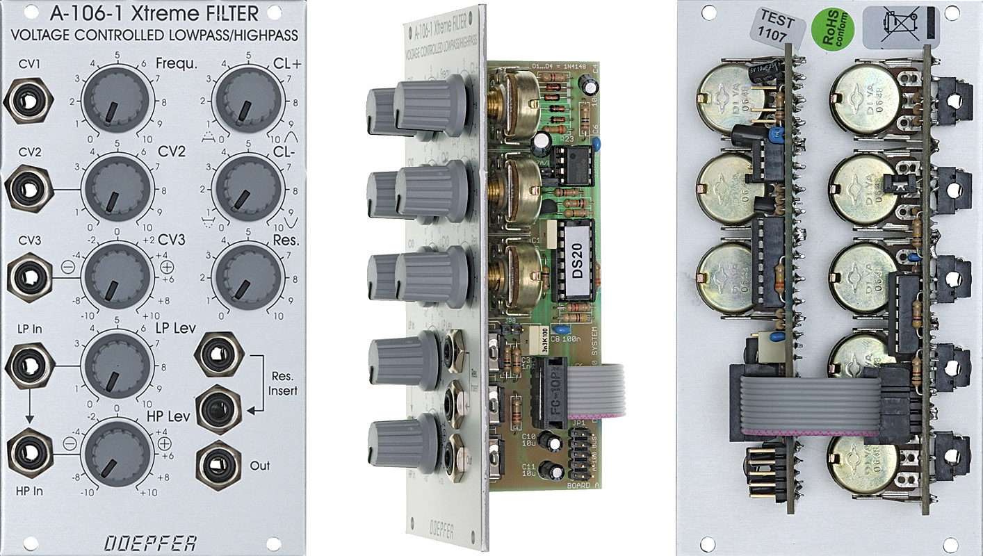
A-106-1 Xtreme Lowpass/Highpass Filter
 click to enlarge |
 |
Module A-106-1 has it's origin in our experiments to built a MS20 filter clone. The module is not exactly the same as the MS20 filter but similar. The famous original MS20 included two filters: a 12 dB lowpass and a 6dB high pass filter connected in series both with a very special design (the MS20 highpass if very often described as 12dB high pass, but this is not true). During our researches we found a way to use the same circuit simultaneously as lowpass and highpass for 2 different audio signals (a bit similar to the A-101-1 Steiner Vactrol filter that has even different audio inputs available, but with the special MS20 circuit). For this two separate audio inputs for lowpass (LP) and highpass (HP) with separate level controls are available. The sockets are normalled, i.e. the signal applied to the LP input is available for the HP input too provided that no plug is inserted into the HP input socket. The level control of the HP input is realized as a polarized input. This means that the signal can be added with the same polarity (+ range) or opposite polarity (- range) compared to the LP input. This feature enables notch (+) and bandpass (-) filter functions too. From our point of view this is the most flexible solution that enables e.g. these functions:
- Lowpass: the audio signal is fed to the LP input, HP level control is set to zero, LP level control is set to the desired level
- Highpass: the audio signal is fed to the LP or HP input, LP level control is set to zero, HP level control is set to the desired level (in this special case it does not matter if positive or negative amplification is chosen with the polarizer control)
- Lowpass/highpass mix with one audio signal: the audio signal is fed to the LP input, LP and HP level controls
are set to the desired levels.
- special setting 1: if the level controls for LP and HP are set in a way that both levels are identical with the same polarity (i.e. + range of the HP level control) and no or little distortion only one obtains ~ a notch filter (the "~" indicates that the notch is far from beeing perfect, the attenuation in the passband is not as good as for other filters of the A-100 system, look at the frequency response curves at the bottom of this decoment for details)
- special setting 2: if the level controls for LP and HP are set in a way that both levels are identical with the opposite polarity (i.e. - range of the HP level control) and no or little distortion only one obtains ~ a bandpass filter (the "~" indicates that even the bandpass is far from beeing perfect, there is a significant feedthrough of frequencies below and above the center frequency, look at the frequency response curves at the bottom of this decoment for details)
- Remark for settings 1 and 2: The original MS20 circuit was not planned for notch or bandpass applications. The ~notch and ~bandpass filters should be treated as a free bonus and have the disadvantages mentioned above. The reason is that the lowpass has a 12dB/octave slope and the highpass 6dB/octave. This leads to phase relations that do not allow a "perfect" bandpass and notch simply by adding/subtracting signals as for other filter designs (for insiders: there remains always a 90 degree phase shift). For better notches and bandpasses other A-100 filters should be used - or two A-106-1 patched in series (bandpass) or parallel (notch) with suitable frequency settings.
- Lowpass and highpass with two different audio signals: the two audio signals are fed to the LP input resp. HP input, the level controls for LP and HP are set to the desired levels. For the +/- control of the HP input it is essential in this case if the two input signals are phase correlated (e.g. two different outputs of the same VCO or VCO output and a frequency divided signal derived from this VCO) or there is no fixed phase correlation between the two signals (e.g. two different VCOs). In the first case the the - and + range of the HP control leads to different filter results. In the second case there is no difference if the + or - range of the HP control is used.
This design allows even some very special
functions: It is e.g. possible to adjust the controls so that the LP signal does
not distort but the HP share does (or the other way round) -
alternatively with the same or opposite polarity compared to the LP signal. For
this the LP level has to be set to a small value so that the signal does not
distort. The HP level control has to be set to a higher value (in the + or -
range) so that the HP share will distort.
The variety of controls allows a lot of functions that are not available for any
other filter we know.
During the A-106-1 development we found also that it might be useful to add controls not available in the original
filter design. In the original circuit
the filter output level is limited to about +/- 0.7V by two antiparallel diodes across the
output/resonance amplifier. By chance we discovered that removing one or both diodes leads to noticeable different behaviour of the filter. Moreover we
added two rotary controls CL+ and CL- to adjust the effect of each
limiting diode (from
original filter behaviour, i.e. fully active limiting diodes, to no limiting
effect). The independent control for each diode allows asymmetrical
limiting/amplification
that causes a completely new and sometimes very strange behaviour. One of the
main effects of the asymmetrical limiting is that in self-oscillation the filter does
not generate a sine
wave but short pulses if only one of the limiting diodes is activated. Another
effect is that a higher output of the filter can be obtained (limited to about
+/- 0.7V for the original circuit). In addition dirty
noise effects appear at certain combinations of the control settings for
resonance, CL+, CL- and input level. The controls CL+, CL-, Resonance, LP
level and HP level have be looked at always in a common context: if the input
levels are small the CL+ and CL- controls will have no effect as the signal does
not distort at all. Increasing the resonance also increases the audio level and
the CL+/CL- controls may now have an effect without changing the input level !
Same applies if the resonance control remains unchanged but the input level is
increases. Now the CL+ or CL- control will have an effect as the level reaches
the clipping thresholds. Increasing the audio level does also suppress the
resonance if distortion becomes extreme. The "teamwork" of the five
controls is very complex and has to be learned by doing and hearing.
The audio inputs are very sensitive to allow even extrem distortion effects,
much more than possible with the original filter design.
We also expanded the module by an insert option for the resonance feedback loop.
This allows to insert other A-100 modules into the resonance circuit. The
standard application is to insert a VCA for voltage controlled resonance. But
even other modules - e.g. waveshaper, divider, phaser, distortion, PLL,
wave multiplier, spring reverb, ring modulator, frequency shifter ony any other audio processing module - can be
inserted to obtain sounds you have never heard before.
On top of this the module is equipped with two frequency CV inputs. One is carried out as a polarizer. This means that effect of the external CV (e.g. envelope from an ADSR A-140 or A-141) to the filter frequency is positive (+ range) or negative (- range). Especially when the filter is moved from LP to HP it might be useful to invert the polarity of the envelope CV. We also have to mention that the frequency response if far from 1V/oct but rather non-linear.
To obtain the filter section of the original MS20 two A-106-1 have to be patched in series (one in LP mode, the other in HP mode, both with CL+ and CL- set to zero).
It has to be pointed out that the A-106-1 is far away from being a "perfect" filter in an academic sense: The control scale is non-linear. With self-oscillation all sorts of waveforms except sine are generated. With high distortion and resonance settings a lot of roaring/rattling/noise or other unpredictable sounds may appear. High distortion/level may "kill" the resonance at certain settings. The filter has a significant control voltage feedthrough and is noisy. The "bandpass" is not a real band pass as a considerable share of all frequencies passes through. The notch filter does attenuate only about 50% at the center frequency - and many more. But the A-106-1 has a lot of character - much more than any other filter of the A-100. It is a very strange and awesome filter - somehow exactly the contrast to the A-108, which is a very smooth, warm and predictable filter. The A-106-1 is definitely not the right choice for "moogish" and "civilized" sounds but for extreme, exceptional and experimental sounds - this is why we call the module "X-Filter". If you want to know more technical details please look at the A-101-1 technical details. In this document the basics of the A-101-1 (Steiner) and A-106-1 filter are described.
Included options: For the HP input control can be chosen if the polarizer is active or if a normal attenuator is available. For some applications it might be useful to have the level controls of LP and LP work in the same way (e.g. to obtain the same level for both inputs). With a jumper on the pc board the type of HP level control can be chosen. The CL+ and CL- parameters are prepared to be controlled by external vactrols. Two pin headers are used to establish a connection to the universal vactrol module that is still under development. This will allow voltage control of the CL+ and CL- parameter.
Application ideas:
- Using the VC panning module A-134 for voltage control of filter type (audio input -> audio in A-134, left output A-134 -> LP input of A-106-1, right output A-134 -> HP input A-106-1, CV of A-134 controls A-106-1 filter type)
- Voltage controlled polarizer A-133 instead of manual control of CV2 or HP level
- different external audio processing modules for the resonance feedback loop
Why the number A-106-1 is chosen for this module? As we think about an MS50 filter clone too ....
A detailed description of the module can be found in the user's manual
![]() A1061_man.pdf
A1061_man.pdf
Audio Examples
The following audio examples show some of the possibilities of the module (so far only sounds with one audio source available, examples with two different audio signals for lowpass and highpass input follow soon).
The first three examples are recorded in low pass mode with the following patch: A-110 VCO and A-140 ADSR controlled by an A-155 sequencer, VCO Out = Audio In of A-106-1, ADSR Out = CV In of A-106-1. For all three examples the filter frequency is turned manually from minimum to maximum, then turned back by simultaneous addition of ADSR CV. No other parameter is changed within one example. The A-155 sequence is the same for all three examples:
A106_nores_noclip.mp3:
Standard low pass
mode without clipping and no resonance.
A106_hires_loclip.mp: Standard
low pass
mode with a bit of clipping and with high resonance
A106_hires_clip_both.mp3: Module
in low pass mode with asymmetrical limiting (one limiting diode deactivated, the other one
with moderate limiting) and self oscillation. The roaring/rattling at the
beginning of the sample are the self oscillation pulses generated by the A-106-1
in this setting (no the incoming VCO signal). As the filter frequency increases
the VCO sequence becomes audible. With these setting very strange and noise
sounds can be generated (e.g. sounds like defective tube equipment or power
amplifier becoming defective).
The next three short examples are recorded in high pass mode with the following patch: A-110 VCO and A-140 ADSR are controlled by an A-155 sequencer, VCO Out = Audio In of an A-131 VCA controlled by the A-140 envelope, A-131 out = A-106 audio in, frequency of A-106-1 modulated by the triangle output of an A-145 LFO. No parameter is changed manually within these examples:
A106_HP_nores_noclip.mp3:
Standard high pass
mode without clipping and no resonance.
A106_HP_midres_noclip.mp3: Standard
high pass
mode with medium resonance without clipping
A106_HP_hires_clip.mp3: Module
in high pass mode with symmetrical limiting and high resonance resp. self oscillation. The
same roaring/rattling/defective sound as for the low pass is possible for high
pass too but not used in this example.
The next examples shows the module as a notch
filter. The sawtooth output of an A-110 is the audio input of the A-106-1.
The frequency is modulated with a triangle LFO (A-145). No resonance. Not very
exciting but it shows the varying capabilities of the module: A106_Notch.mp3
The next examples show the simultaneous usage of lowpass and highpass. The
same patch as for the first examples is used. Some parameters are changed
manually during the examples:
A106_LP_fade_in_HP.mp3:
This example starts as lowpass and little by little the highpass level is
increased. Lowpass level remains unchanged.
A106_HP_to_LP_fade.mp3: This
example starts as highpass with high filter frequency and small resonance. These
manual control changes are made one after another: filter frequency decrease -
resonance increase - highpass level decrease and simultaneously lowpass level
increase - resonance decrease - resonance increase- resonance decrease again and
simultaneously envelope amount decrease.
The next example shows the usage of a spring reverb A-199 with VCA A-130 in the feedback loop. Again the same sequence as in the first examples is used. The two stored random voltages of an A-149-1 are used to control the VCA (that controls the reverb feedback) and the filter frequency of the A-106-1. This brings a lot of liveliness in the sequence. The A-149-1 is triggered by the same clock source as the sequencer. No parameter is changed manually during the example! All changes are caused by the A-149-1 only:
A106_spring_fb_sou.mp3: Example with spring reverb in feedback loop, amount of feedback controlled by a random voltage
http://blog.andreaskrebs.de/2010/06/18/doepfer-a-106-1-xtreme-filter-example/
|
A-106-1 Frequency response curves |
|
 |
 |
| Lowpass (no resonance) | Highpass (no resonance) |
 |
 |
| ~ "Bandpass" | ~ "Notch" |
 |
 |
| Lowpass (with medium resonance) | Highpass (with high resonance) |
Tiefe/Depth: 40 mm (gemessen ab der Rückseite der Frontplatte / measured from the rear side of the front panel)
Strombedarf/Current: +30mA (+12V) / -20mA (-12V)
The price in US$ depends upon the exchange rate between Euro and US$ at the payment day.