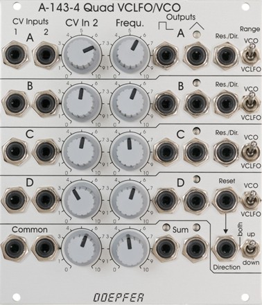
A-143-4 Quad VCLFO/VCO
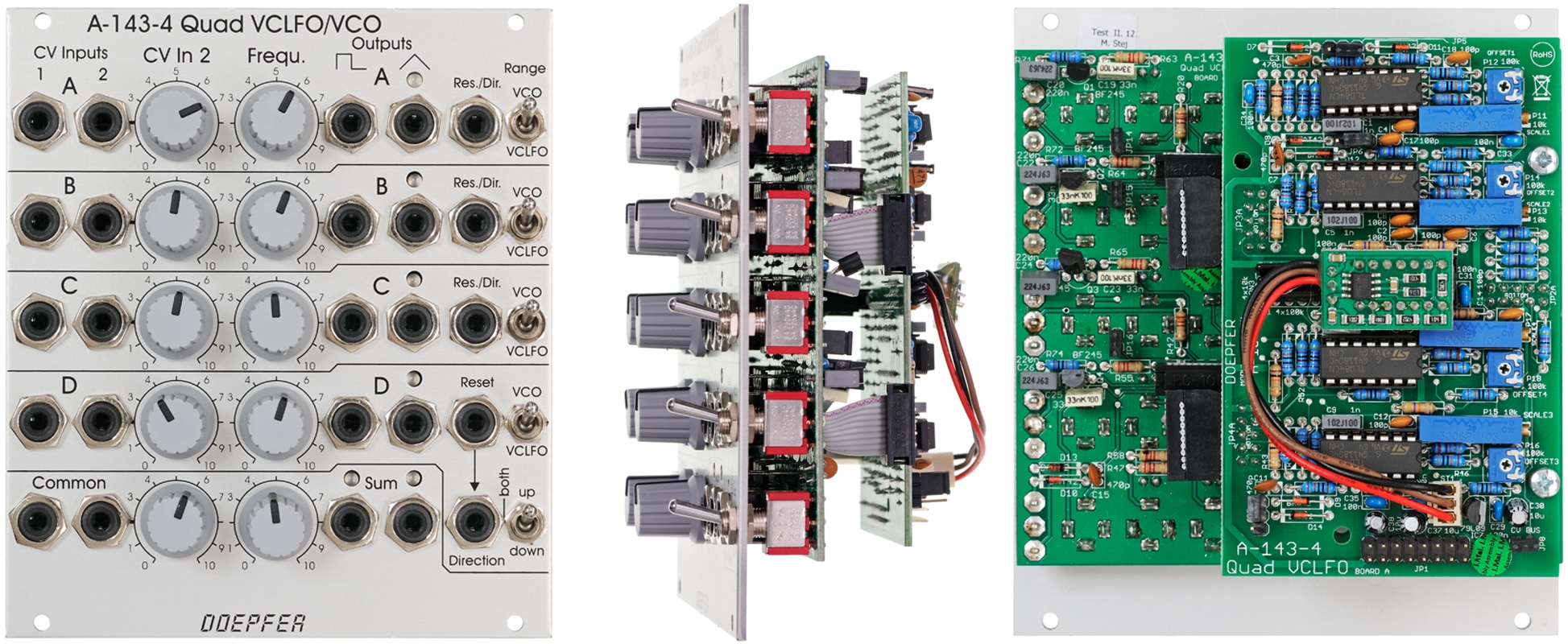 click to enlarge |
|
Note: The
labelling of the range switches of the front panels of the first module series
was reverse. The
up position is high (VCO mode), the down position is low (LFO mode)
From the second series the front panel printing is correct (like the above
picture)
- four independent VCLFOs/VCOs with triangle core
- frequency range switches: low (bottom position) = LFO mode, high (top position) = VCO mode
- two frequency control CV inputs for each unit
- CV1 without attenuator (~ 1V/oct)
- CV2 with attenuator
- manual frequency control
- internal jumpers for the frequency range of
the manual frequency controls:
- jumper not installed: ~ +/- 1 octave range (mainly for VCO applications)
- jumper installed: ~ +/- 5 octaves range (mainly for VCLFO applications)
- Sync inputs:
- combined Reset/Direction inputs for unit #1 - #3
- separate Reset and Direction inputs for unit #4 (normalled sockets, i.e. Reset is connected to Direction if the Direction socket is unused)
- up/both/down direction switch for unit #4, for technical details concerning the Reset and Direction function please refer to the sketch below
- triangle and rectangle outputs for each unit
- typ. output voltage range -5V ... +5V for both outputs (i.e. about 10 Vpp, symmetrical with reference to 0 V)
- red/yellow LED displays for the triangle outputs (red = negative output voltage, yellow = positive output voltage)
- common control section with two CV inputs and manual control (these inputs and controls affect the frequency of all four units)
- sum outputs for triangle and rectangle with red/yellow LED displays
- optional ultra-low frequency mode: for this a negative voltage can be applied via a jumper internally to the CV2 input of each unit and the common section (i.e. a negative voltage is normalled to the socket CV2 in question). Then the CV2 attenuator control works as a negative frequeny control (i.e. turning up this control lowers the frequency). Herewith LFO periodes up to about one hour (or even more) are possible.
- optional CV bus access via jumper (i.e. the module can pick up the CV from the A-100 bus, e.g. generated by a Midi/CV or USB/CV interface A-190-x or a bus access module A-185-1/2), if the jumper is installed the bus CV affects all four units as the bus CV is added to the CV generated by the common control section
- typ. frequency range: < 0.001 Hz (~ one hour, LFO mode with ultra-low option) ... 15 kHz (VCO mode with installed frequency range jumpers for the manual frequency controls)
- heat-up time: ~ 15 minutes (required to heat-up the main circuit by the affixed oven)
Important Notes:
The module was planned
mainly as a quad
VCLFO. But we added a range switch (nothing but a switch for
two different capacitors) so that even audio frequencies are possible and the
module can be used as VCO with some restrictions too. Because of the closeness of the main circuitry (i.e. four VCO cores within less
~ 1 square millimeter) the oscillators may lock if the
frequencies are very close to each other and the VCO frequencies interact
marginally. If a high quality quad VCO is required the A-111-4
is recommended as this module has four separate VCO circuits available.
The reset circuitry is optimized for
the LFO mode. As it takes some time to discharge the oscillator capacitor the discharge time
had to be chosen so that the capacitor is fully discharged in LFO mode. In the
high range (where a much smaller capacitor is used) this will cause a zero state
duration in the 0.3 ms range if the oscillator is synced (during this time the
capacitor is shortened for discharge).
The control scale of the inputs "CV1" is about 1V/octave. To improve
the behaviour in the VCO mode a tempco circuit is used to keep the temperature
of the exponential converter at a fixed temperature (similar to the tempco option of the DIY
SYNTH).. That way the frequency of the
VCOs (and even the VCLFOs) is nearly independent from the environment
temperature. But the accuracy (1V/octave scale and temperature compensation) is
not as precise as for the dedicated VCOs A-110 and A-111-1.
This document explains the functions of the 17 jumpers: A143_4_jumper.pdf
Technical details concerning the Reset and Direction function:
The reset of a triangle based LFO or VCO consists usually of two functions:
- Discharge of the capacitor that is used to generate the oscillation (i.e. set the output voltage to 0V)
- Pushing the LFO into the right direction. Usually an LFO starts from zero with it's positive slope after a Reset. Without this second function the LFO would randomly start with positive or negative slope (exactly: it would keep the direction that was present while the Reset has been carried out)
For unit #4 all types of sync are available:
- Separate Reset and Direction function (separate, normalled input sockets for Reset and Direction)
- Direction switch up/both/down
- In the up position only a direction change to rising slope is possible (triggered by the rising edge of the direction signal)
- In the down position only a direction change to falling slope is possible (triggered by the falling edge of the direction signal)
- In the both position both direction changes are possible (the positive edge of the direction signal causes a change to the rising slope, the negative edge of the direction signal causes a change to the falling slope)
- the direction signal causes only an effect if the slope is not yet in the direction in question (e.g. the rising edge of the direction signal has no effect if the LFO signal is already in the rising stage)
Tiefe/Depth: 60 mm (gemessen ab der Rückseite der Frontplatte / measured from the rear side of the front panel)
Strombedarf/Current: +100mA (+12V) / -100mA (-12V)
The price in US$ depends upon the exchange rate between Euro and US$ at the payment day.