A-178 Theremin Control Voltage Source
|
|
|
|
|
|
|
|
|
|
Standard Edition |
Vintage Edition |
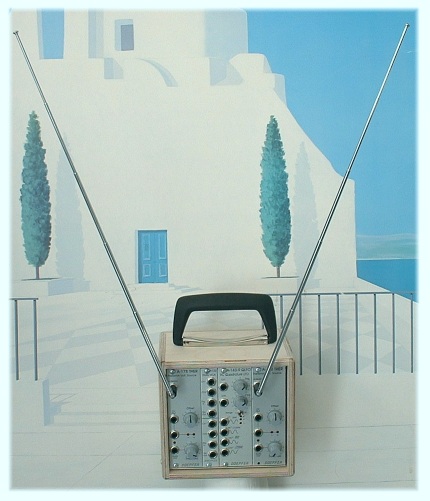
Theremin-Modul
zum Erzeugen einer variablen Steuerspannung über Annäherung der Hand an eine Antenne.
Die Reichweite beträgt ca. 30-40 cm. Weiterhin ist ein Gate-Ausgang verfügbar, der ab einer einstellbaren Ausgangsspannung
(Threshold) anspricht, um z.B. einen Hüllkurvengenerator zu triggern oder einen VCA
anzusteuern (an/aus).
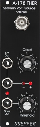
Bedienungselemente: Antennen-Eingang, Offset (Drehregler für Nullabgleich), 2xCV-Ausgang,
2xLED (für CV-Anzeige positiv/negativ und Einstellung des Null-Abgleichs), Threshold
(Gate-Schwelle), Gate-Ausgang, Gate-LED
Zur Nachbildung des Original-Theremin werden zwei A-178, ein VCO (z.B. A-110) und ein
linearer VCA (z.B. A-130 oder A-132) benötigt. Ein A-178 steuert die Tonhöhe (VCO), das
zweite die Lautstärke (VCA). Das A-178 bietet sich jedoch an, auch andere Funktionen im
A-100 zu steuern (z.B. Filterfrequenzen, Modulationen, Tempo, Ein/Ausschwing-Zeiten usw.).
Der Spannungsbereich des CV-Ausgangs reicht - je nach Einstellung des
Offset-Regler von maximal -10V bis +10V. Der Gate-Ausgang schaltet zwischen 0V
und ca. +10V.
Die deutsche Bedienungsanleitung ist als PDF-Datei auf unserer Website verfügbar: A178_anl.pdf
Anwendungen:
- Steuerung beliebiger analoger Parameter im A-100 (z.B. Tonhöhe mit VCO A-110, Lautstärke mit VCA A-130/131/132, Panorama mit A-134, Filterungen mit A-120/121/122/123, Phasing mit A-125, Frequenz-Verschiebung mit A-126, Hüllkurven-Parameter mit A-141/142, Tempo über A-147).
- Auslösen bestimmter A-100 Funktionen durch die Gate-Funktion mit einstellbarer Schwelle, z.B. Starten einer Hüllkurve (A-140/141/142), Start/Stop-Funktionen von Sequenzer, beliebige Umschaltfunktionen mit A-150/151.
- Umwandlung im MIDI-Controller-Befehle mit Hilfe des A-192 möglich
Wichtiger Hinweis: Falls zwei oder mehr A-178 eingesetzt werden, sollten diese einen Abstand von mindestens 40-50 cm haben, damit sich die Antennen nicht gegenseitig beeinflussen.
Technische Hinweise:
Das Modul benötigt zum Betrieb eine hochwertige Stromversorgung (kein einfaches, billiges Schaltnetzteil sondern bevorzugt ein linear geregeltes Netzteil, wie etwa A-100PSU2 oder A-100PSU3), sowie ein geerdetes Gehäuse, so dass die Frontplatte des Moduls mit Masse verbunden ist. Andernfalls funktioniert die empfindliche Theremin-Schaltung nicht korrekt!
Es ist nicht möglich, die Antenne über ein Kabel anzuschließen oder durch ein anderes Element zu ersetzen. In diesem Fall wird das Modul nicht mehr richtig funktionieren. Die Antenne bildet zusammen mit der Hand einen veränderlichen Kondensator mit sehr geringer Kapazität im Pico-Farad-Bereich und die Elektronik ist genau darauf abgestimmt. Durch das Einfügen eines Verlängerungskabels oder das Ersetzen der Antenne durch ein anderes Element würden sich die Kapazitätswerte völlig ändern und das Modul arbeitet dann nicht mehr korrekt. Es ist jedoch möglich bei Bedarf das gesamte Modul mit Hilfe eines längeren Buskabels an der gewünschten Stelle zu platzieren, beispielsweise in einem kleinen Gehäuse in dem ein oder zwei Module montiert werden. Wir können ein längeres Buskabel auf Anfrage als Sonderanfertigung herstellen (bitte ggf. die gewünschte Länge für ein Angebot angeben).
Seit August 2012 kommt eine sog. BNC-Verbindung für den Anschluss der Antenne zum Einsatz (wie z.B. bei Messgeräten wie etwas Oszilloskopen verwendet). Der Umbau eines älteren Moduls (mit 3,5 mm Klinkensteckverbindung für die Antenne) auf die neue Art der Steckverbindung ist zwar möglich, erfordert aber etwas mechanisches und elektrisches Geschick. Das Modul muss hierzu komplett zerlegt werden, um ein zusätzliches Loch für den BNC-Steckverbinder in die Frontplatte zu bohren oder zu stanzen (z.B. rechts von der vorhandenen Antennenbuchse über dem Offset-Regler). Das vorhandene alte Loch des Antennenanschlusses kann für die BNC-Verbindung nicht verwendet werden ! Dann wird das Modul wieder zusammengebaut und der zusätzliche BNC-Steckverbinder mit der vorhandenen Antennenbuchse verbunden. Bitte beachten Sie, dass unbedingt ein isolierter BNC-Steckverbinder verwendet werden muss ! Geeignet sind z.B. die Typen UG1094PL, UG1094PR, UG1094W1 oder UG1094W2 erhältlich bei www.reichelt.de oder unter der Bestellnummer 571-5413194-2 von Mouser, Farnell, RS-Online oder anderen Lieferanten.
Ähnliche Steuerspannungs-Module:
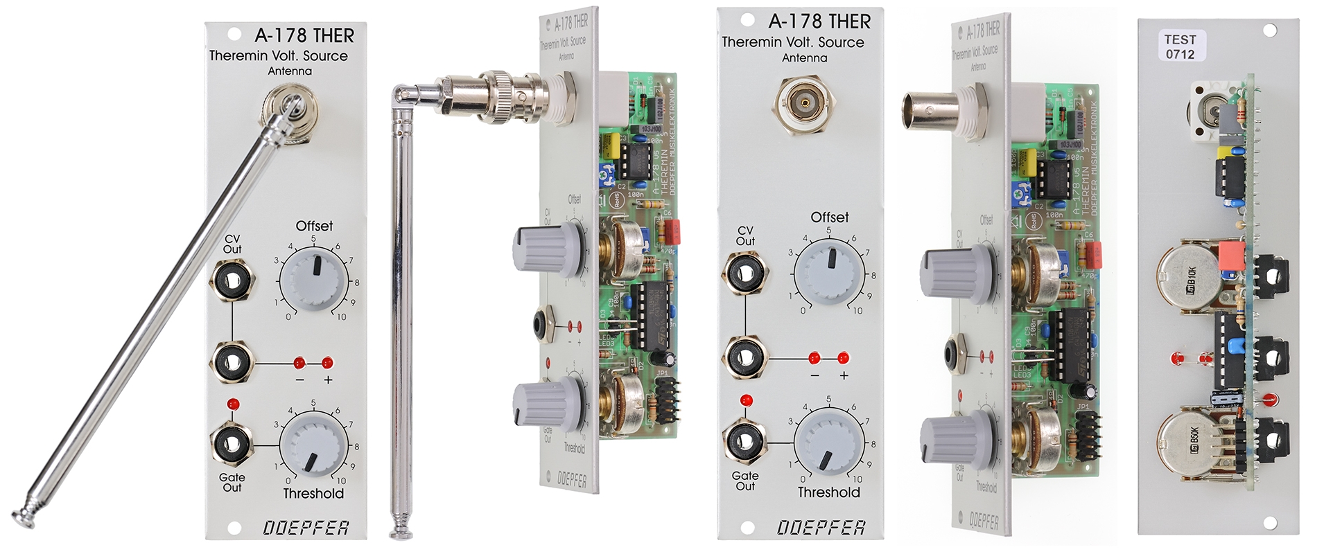 new Version with BNC connection |
|
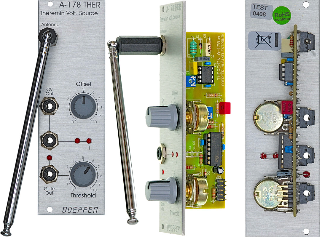 old version with 3.5 mm jack socket |
|
|
|
|
|
Standard Edition |
Vintage Edition |
Theremin module for generating a variable
control voltage by approaching/removing hand to/from an antenna. The distance
range is about 30-40 cm. Additionally the module
is equipped with a Gate output with adjustable threshold level. Controls/Inputs/Outputs: antenna input, offset (knob for zero adjust),
2 x CV out, 2 x LED (for CV control positive/negative and zero offset adjust)
To simulate the original Theremin two A-178, a VCO (e.g. A-110) and a linear VCA (e.g.
A-130 or A-132) are required. But of course the A-178 can be used to control other
functions in the A-100 (e.g. filter frequency, modulation depth and/or speed, tempo,
attack/decay time and so on).
The CV output voltage of the A-178 can
range - according to the setting of the front panel controls - from
-10V...+10V. The gate output switches from 0V to about +10V.
For more detailed information please look at the English user's manual A178_man.pdf
Applications:
- controlling any voltage controlled parameter of the A-100, e.g. pitch or pulswidth (VCO A-110), loudness (VCA A-130/131/132), panorama (A-134), filter frequency or resonance (A-120/121/122/123), phasing (A-125), frequency shift (A-126), resonance peaks (A-127), envelope parameters (A-141/142), tempo (A-147)
- triggering of A-100 activities via gate with adjustable threshold, e.g. starting an envelope (A-140/141/142), Start/Stop of a sequence (A-155), any switching function (A-150/151)
- Conversion into MIDI control change messages
is possible with the A-192.
Remark: If two or more A-178 are used the distance between the modules/antennas should be at least 40-50 cm. Otherwise the antennas may affect each other.
Technical Notes:
The A-178 requires a good power supply (not a cheap switching power supply, a linear regulated power supply like the A-100PSU2 or A-100PSU3 is preferred) and a housing that is connected to GND so that the front panel of the A-178 is also grounded. Otherwise the sensitive Theremin circuit will not work properly!
It's not possible to connect the antenna via an additional cable to the antenna socket or to replace the antenna by another element. Antenna and hand form a variable capacitor with a very small capacity in the pico Farad range. The electronics of the module is puzzled out just for this capacity range. If a cable is added or the antenna is replaced by another element the capacity range changes totally and the module will no longer work ! But it's possible to mount the complete module with antenna at the desired position, e.g. into a small case that holds one or two of the modules. It's also possible to use a longer bus cable to connect the module to the A-100 bus. If you are not able to manufacture such a cable yourself we may offer a suitable cable upon request. Please tell us the desired length for a quotation of such a cable.
From August 2012 an improved version for the antenna connector is used. Instead of the 3.5 mm miniature jack socket of the old version a so-called BNC connector is used to connect the antenna to the module (same type of connector as used in measuring equipment like oscilloscopes). Some mechanical and electrical skills are required to modify an existing A-178 module for the new version of the antenna connector. The module has to be completely disassembled. An additional hole for the new BNC connector has to be drilled or punched into the panel e.g. right from the existing antenna socket above the Offset control (the existing hole of the 3.5 mm miniature socket cannot be used for the BNC connector). Then the module has to be assembled again and the new BNC connector has to be connected to the old socket. Pay attention that an isolated version of the BNC socket has to be used. For example the BNC connectors UG1094PL, UG1094PR, UG1094W1 or UG1094W2 can be used. In Germany the connectors are available e.g. from www.reichelt.de or using e.g. the order no. 571-5413194-2 from Mouser, Farnell, RS-Online or other suppliers).
Similar control voltage modules:
Breite/Width: 8 TE / 8 HP / 40.3 mm
Tiefe/Depth: 40 mm (gemessen
ab der Rückseite der Frontplatte / measured from the rear side of the front
panel)
Strombedarf/Current: +60mA (+12V) / -20mA
(-12V)
Standard Version : Euro 110.00
Vintage Edition : Euro 120.00
Ersatzantenne (alte Version mit 3,5 mm Klinkenbuchse) / replacement antenna (old version with 3.5 mm jack plug): Euro 20.00
Ersatzantenne (neue Version mit BNC-Verbindung / replacement antenna (new version with BNC connector): Euro 25.00
The price in US$ depends upon the exchange rate between Euro and US$ at the payment day.
A-178 Theremin videos by our customer Jamie O'Callaghan:
http://uk.youtube.com/neonwind
www.youtube.com/v/jsqNvR3jLdY&hl=en&fs=1
www.youtube.com/v/A1BsIGzkzzs&hl=en&fs=1
www.youtube.com/v/czFto0B8ARs&hl=en&fs=1