 |
|
| schematically | Photo (the photo shows the old version of the power supply with 650mA only |
|
A-100 Construction Details |
The A-100 modular system is based
on the international standard 19" rack system (DIN
41494 / IEC 297-3 / IEEE 1001.1). Doepfer
only offers ready built A-100 frames, i.e. with built in power supply, bus
boards, top/bottom/rear cover, mains inlet, power switch and fuse holder. We
do not offer single mechanical parts of the A-100 frames (like mounting
rails). The
metal parts of the standard frames used in the A-100 are manufactured by the
German company Gie-Tec (https://gie-tec.de).
If you want to built your own frames or need additional accessories you may
order directly from Gie-Tec or from an electronic shop (e.g. Conrad, Reichelt,
Buerklin in Germany, or Mouser in USA).
Individual modules
can be fitted in any chosen layout into the 19" frame. The standard 6U rack
system consists of two
sections each 3U high, tied together by 6U side panels. The 6U version is
available as portable suitcase version too. It
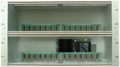
contains two bus boards (1), the standard power supply with +/-12V@1200mA (2) , the main electrical supply socket (3) and all required
interconnections between (1), (2) and (3). A small 3U rack is
available too (only one bus board, no portable suitcase version available). For old systems or frames manufactured before
2006 even the old power supply with 650mA only may be in use !
|
|
| schematically | Photo (the photo shows the old version of the power supply with 650mA only |
Fig.1: View into the A-100G6 basic frame
Module front panels are all 3U high (1U = 1.75 inch = 1.75" = 44.45mm, 3U = 133.4 mm). The final height of the front panels is a bit less than 133.4 mm as the rim of the mounting rails has to taken into considerattion. Consequently the final height is 128.5 mm for all A-100 front panels. Their width is measured in HP (HP = horizontal pitch, 1 HP = 5.08 mm or 1/5 inch or 1/5"). The actual width of a front panel is a few tenth of a mm less than the calculated value (i.e. multiple of 5.08 mm resp. multiple of 1/5") to have a little bit tolerance to assemble the panels. The table below shows the actual widths for the most common front panel measures and the position of the mounting holes relative to the front panel edges. For the front panels up to 10 HP two mounting holes are sufficient (one below, one above). From 10/12 HP usually four mounting holes are used. The horizontal distance of the mounting holes has to be a multiple of the HP grid, i.e. a multiple of 5.08 mm resp. 1/5" (= N x 5.08 in the sketch below). To assemble the modules in the frame M3x6 oval-head screws with cross recess (DIN7985) are used. The front panels are made of 2 mm anodized aluminium.
|
Position of the mounting holes |
Module width [HP] |
calculated
module width
[mm] |
actual module width [mm] |
|
 |
1 |
5.08 |
5.00 |
|
| 1.5 | 7.62 | 7.50 | ||
|
2 |
10.16 |
9.80 |
||
|
4 |
20.32 |
20.00 |
||
| 6 | 30.48 | 30.00 | ||
|
8 |
40.64 |
40.30 |
||
|
10 |
50.80 |
50.50 |
||
|
12 |
60.96 |
60.60 |
||
|
14 |
71.12 |
70.80 |
||
|
16 |
81.28 |
80.90 |
||
| 18 | 91,44 | 91,30 | ||
|
20 |
101.60 |
101.30 |
||
|
21 |
106.68 |
106.30 |
||
|
22 |
111.76 |
111.40 |
||
|
28 |
142.24 |
141.90 |
||
|
42 |
213.36 |
213.00 |
Table 1: Position of the mounting holes and front panel width in HP and mm
The rack system has a usable width of 84 HP (= 426.4 mm). If the modules you install don’t use up the entire 84 HP, then you must cover up the spaces with blanking panels (see A-100 accessories) due to safety and EMC reasons. In the description for each module (e.g. A-110) you will find the width of the module in HP measures.
| Available blind front panels | ||||
| no picture available | ||||
| A-100B1: 1 HP | A-100B2: 2 HP | A-100B4: 4 HP | A-100B8: 8 HP | A-100B42: 42 HP |
Rack system construction details:
Fig.2
In detail the 6HU rack system is
made of the following components:
(1) front rail version 1 (with lip), with threaded inserts (for
module mounting)
(2) front rail version 1 (with lip), with slide nuts (for rear
covers mounting)
(3) front rail version 2 (without lip), with slide nuts (for bus
board mounting)
(4) front rail version 2 (without lip), for increasing stability
only
(5) side plate
(6) 19" mounting flange
(x) top and bottom cover (not shown in the picture)
A detailed description of the A-100 frame construction is available as pdf document A100G6_e.pdf. Pay attention that this is an internal technical document suitable for qualified personnel or specialists only who are able to ensure the electrical safety of the final construction. On no account beginners or laymans are allowed to assemble frames on the basis of this document. Dangerous mains voltage 115V / 230V. Danger to life !
In each 6HU frame there are two system bus boards (one for each section), to each of which up to 14 modules can be connected, using ribbon cable. The bus bar serves to supply power to the modules, and also to send control voltages etc. to some of the modules. The 3HU frame is half the 6HU (only one bus board).
 |
A-100 bus board |
The A-100 standard power supply produces voltages of +12 V and -12 V and can put out a maximum current of 1200 mA. (the old version of the power supply only 650 mA). In setting up a modular system, make sure that the total current required by all the modules doesn’t exceed this maximum (you will find the current for each module at the module description). If it does, then a second power supply (see A-100 accessories) will need to be installed (at position (4) fig.1). As a rule, though, one standard power supply should be sufficient for a rack system. Additionally a +5V power supply may be installed at the second back plane (position 4 at fig. 1) if a +5V power supply is required (some modules need +5V too, e.g. A-113, A-190, A-191). Alternatively the +5V low cost adapter can be installed if not more than 100 mA are required at +5V and there is a corresponding current reserve at +12V (the +5V low cost adapter takes the current from +12V). You will find a remark at the module description if the module requires +5V. For details regarding +5V power supply or +5V low cost adapter look at A-100 accessories.
If you want to run only one or a few modules the A-100 Miniature Power Supply can be used instead of the A-100 standard power supply (see A-100 accessories). It supplies max. 200mA@+12V/-12V and additionally 50mA@+5V. The A-100 Miniature Power Supply is also available built into the A-100 Miniature Case. If this is not used the customer has to find himself a suitable mechanical solution for installing the modules. But as no mains voltage appears at the miniature power supply there is no danger to life (an AC adapter with 9V AC output is used).
We also offer DIY kits for customers who want to built their own cases. The kits include a power supply, one or two bus boards and front rails that allow to mount the modules in the case.
The standard power supplies are available as spare parts too. Because of the mains voltages (115 or 230V AC) appearing at the standard power supplies they are allowed to be installed only by qualified personnel that is able to keep the valid safety rules. Danger to life ! If you want to built your own cases we strictly recommend to use the power supply of the A-100 DIY-Kit or the A-100 Miniature Power Supply.
An overview of all A-100 accessories is available here: A-100 accessories
Installing modules
Important: Before you install a module into the rack system:
Ignoring this warning can result in damage to your system, and will void your guarantee!
Once you’ve checked that there is sufficient current in reserve for the extra module/s, there’s nothing to stop you going ahead and installing them. Read on!
First of all, take the A-100’s plug out of the wall socket.
Plug the supplied ribbon cable into the module’s bus socket (see (1) in Fig. 3). As a rule, the cable is 16-way, but some modules only have a 10-way cable. Look carefully at the cable, and then press the appropriate connector onto the module’s bus pins (see (2) in Fig. 3).
Fig.3: Connection the module to the bus connector
Check very carefully that it is connected so that the coloured marking on the ribbon cable is at the bottom of the module’s connector (see (3) in fig. 3), and that the connection is perfect, and pushed fully home, not at a slight angle. Failure to check this may result in the module’s instant destruction as soon as the power is turned back on.
Fig. 4: Connecting the module's ribbon cable to the bus board
Now join the free end of the ribbon cable (see (2) in fig. 4) to the nearest available position on the system bus board (see (1) in fig. 4).
Check very carefully that it is connected so that the coloured marking on the ribbon cable is at the bottom of the bus connector (see (3) in Fig. 4), and it is pushed fully home, not at a slight angle. Failure to check this may result in the module’s instant destruction as soon as the power is turned back on!
When you’re installing extra
modules, it may be necessary to take another module or two out,
to allow you easier access to the bus board.
Place the module carefully into the space in the rack, and fasten
it firmly in place with the supplied screws. Put back any covers
or blanking plates, and screw them in firmly.Now plug the system
A-100 back into the main power supply, and switch it on.
Test out the newly installed module.
If it doesn’t seem to be working as expected, immediately
disconnect the system from the power supply again.
In this case, double-check the connections, making completely
sure that the ribbon cable is the right way round where it
connects to the module and the bus.
Interconnecting modules
For connecting modules to each other, you need mono miniature jack (Æ 3.5 mm) patch leads. You can obtain patch leads from us in different lengths and colors: 30cm, 50cm, 80cm and 120cm. For details see A-100 accessories.
| Patch cords available in different length, with 2 mono plugs 3.5 mm |
||||
| A-100C30: 30 cm (black) | A-100C50: 50 cm (grey) | A-100C80: 80 cm (red) | A-100C120: 120 cm (blue) | A-100C200: 2m (green) |
| Available only in these lengths and colors. | ||||