|
Technical Details A-100 |
The Principles of Voltage Control
What makes analogue synthesizers (and modular systems in particular) special is that the important parameters of the sound sources (VCO, noise, etc.) and modifiers (VCF, VCA, etc.) can be altered not just by hand, but by voltage control. This principle was turned into reality by the "father of the analogue synthesizer", Robert Moog, who produced the first commercially available synthesizer in the sixties. It gives vast flexibility and the potential to make sounds that have never been made before.
Fig. 1 shows the principle of voltage control, with examples of
control voltages affecting a filter (VCF) and an oscillator
(VCO).
In the case of the VCF, the parameter which is being
voltage-controlled is the Cut-Off Frequency fc.
The amount of control voltage input present changes the cut-off
frequency, and thus the frequency of the signal that the VCF lets
through - see the shaded area in the diagram.
Fig.1: The principles of voltage control
In the case of the VCO, it’s the pitch which is controlled by an external control voltage CV (Control Voltage) : an increase of 1 volt corresponds to an increase of one octave in the pitch. With a sudden change of voltage, the pitch changes suddenly, while with a smoother, continuous change, portamento is created. Pay attention that CV is not an absolute but a relative parameter. A certain CV value (e.g. +1.0V) is not assigned to an absolute pitch ! The resulting pitch of a VCO is the sum of several parameters. The external CV is only one of them. Other parameters that affect the pitch are the tune control (possibly separate coarse and fine tune), an octave switch, additional CV inputs with attenuators which do not follow the 1V/oct standard. Some VCOs are also equipped with controls and control inputs for linear frequency modulation which are also not 1V/oct. Some VCOs also have 2 or more CV inputs which follow the 1V/oct standard (one of these may be provided from the bus). The sum of all these parameters defines the pitch of the VCO.
As well as modules which can be affected by voltage control,
there are other modules like the ADSR and LFO which themselves
produce voltages to control other modules.
Usually, these modules need some kind of a Trigger Signal to bring them
into action. For instance, a GATE Signal, corresponding to
a key being pressed on a keyboard, can set off an ADSR, which
then puts out its variable voltage "envelope" to
affect other modules. The gate level +5V shown in the picture is only an
example. Within the A-100 usually any voltage beyond about +3V is treated as
"high" (e.g. +5V, +8V, +10V, +12V will work) and will trigger an ADSR
or any other module with a Gate or Clock input (e.g. trigger delay, sequencer,
clock divider, clock sequencer). Any voltage below 1V is treated as
"low". If the specification of a module differs from this voltage
standard it is mentioned in the description of the module in question.
Fig. 2: The envelope generated by an ADSR
Signals in the A-100
In the System A-100 there are three types of signal:
- Audio Signals
- Control voltages
- Trigger voltages
Audio Signals are produced
by the sound source Modules (such as VCO or NOISE), and are typically in
the 10Vpp range (from -5 V to +5 V). In
addition the signal levels are usually specified in the module description. The System
A-100 can also let you use external Audio Signals (e.g.
Microphone, Electric Guitar, Keyboard).
To interface satisfactorily, the level of external Audio
Signals must be brought up to the A-100’s operating
level.
Module A-119 (External Input), is ideal for this job,
having among other things an internal pre-amp, and two inputs of
different sensitivity.
Control voltages, as produced by modulation sources like
the LFO and ADSR, are typically from -2.5 V to +2.5 V (5 Vpp) for
LFOs, and from 0 V to +8 V for ADSRs. In addition the signal levels are usually
specified in the module description.
Trigger, Gate or Clock Signals, which start a process or
function, are rectangle shaped signals with typical
voltage levels of 0/+5 V. In case of a trigger application normally the rising
edge of the signal used to trigger the event. But all A-100 modules will withstand gate/trigger/clock signals
up to +12V. In addition the required level is usually specified in the
module description. Only rectangle shaped waveforms should be used as
Trigger , Gate or Clock sources (e.g. the rectangle output of an LFO or the
gate/clock output of a midi interface). Signals with slowly rising or falling
edges (e.g. triangle, sine, rising or falling sawtooth) are not suitable for
this application !
These definitions of the various signals, and the distinctions
between them - sound sources and modulation sources - are right
in principle, but a modular system like the A-100 often makes a
mockery of them. In a modular set-up, all of the modules produce
voltages, and can be used as control voltages or triggers, thus
blurring the distinction between the various types.
For example, the output from an LFO can be used as an audio
signal, as a control voltage for a VCF or VCA, or as a trigger
signals for a sequence.
It’s just about true to say that anything can be modulated
by anything else, so that a modular system gives the musician
extraordinary flexibility and individuality.
Power Supply and System Bus
The A-100’s System Bus ,i.e. the bus board(s), supplies power to the modules. The A-100 modules need the voltages +12V and -12V - some older modules additionally +5V (e.g. the old version of A-113, A-190-1, A-191). The bus also carries the internal control signals GATE and CV (details in the chapter below).
|
|
The A-100 system bus |
|
|
|
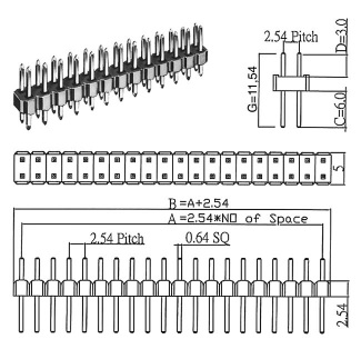
| pin headers used on the bus
boards and the modules (unboxed headers only, without bowl/box and without code gap !) |
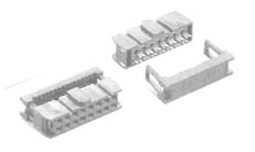
female sockets (pressed to the ribbon cable that are used to connect the modules and the bus board) |
| connectors used for the A-100 bus connections | |
As a rule the -12V line is marked with a colored wire (typically red) and the colored wire has to be aligned to the bottom of the bus board where you find also the -12V imprint.
The voltages +12V and -12V are supplied by the A-100 Power Supply (see A-100 accessories). The power supply is built into the A-100 cases. Three versions of power supplies with different max. supply currents were used over the years:
If a module
requires +5V (e.g. old version of A-113, A-190-1) and A-100NT12 or A-100PSU2 are
installed the +5V low cost
adapter A-100AD5 is required used to generate the additionally required +5V (see A-100
accessories). In this case the required current @+5V is taken from the +12V
line. Of course there has to be a sufficient current reserve at +12V.
In case that the A-100PSU3 is installed the +5V are available anyway and the
additional A-100AD5 is not required.
 |
 |
|
| A-100NT12 | A-100PSU2 | A-100PSU3 |
 |

|
| A-100 bus board | 5V adapter A-100AD5 |
Important note: A-100-modules have to be connected only to original A-100 bus boards or 100% compatible bus boards of other manufacturers ! Particularly it's not allowed to use bus boards with polarized pin headers (boxed pin headers with code gap). These force the user to connect the bus cable in a certain direction which may be the wrong one ! This will destroy the module and the warranty is void ! In the A-100 the colored wire of the ribbon cable marks -12V and this wire has to point to the bottom under all conditions !
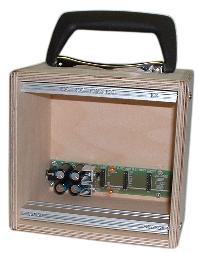
If you want to run only one or a few modules the A-100 Miniature Power Supply may be used instead of the A-100 standard power supply (see A-100 accessories). It supplies max. 200mA@+12V/-12V and additionally 50mA@+5V. We also offer the A-100 Miniature Case with built-in A-100 Miniature Power Supply.
|
|
| A-100
Miniature Power Supply A-100MNT |
A-100
Miniature Case
A-100 MC (with built-in A-100 Miniature Power Supply A-100MNT) |
Meaning and usage of the bus signal CV and Gate
The A-100 system bus also carries the internal control signals GATE and CV. Some remarks concerning the usage of the internal CV and Gate lines of the A-100 bus:
If you want to run single A-100 modules without using our bus board, power supply and frames here is the pin-out for module's bus connectors.
 |
| pin out of the
module's power supply connectors As a rule the -12V line is marked with a colored wire (typically red) and the colored wire has to be aligned to the bottom of the bus board where you find also the -12V imprint. |
Both the 10 pin and the 16 pin version of the bus connection have available the standard power supply (-12V, GND, +12V). In addition the 16 pin version of the bus connection has the three signals +5V, CV and Gate available at the module's connector (e.g. CV is used e.g. in the standard VCO A-110-1 or Gate is used in the envelope generator A-140). Modules that make no use of these additional signals normally use only the 10 pin version of the bus connection.
Pay
attention that applying other than the described voltages or changing the
polarity will result in the module’s instant destruction !
For the connection of the bus cables to the bus the rule is "red strip
down" !
If you use a Midi/CV-Interface in your system, when you press a key on your Midi keyboard, the gate and CV signals from the interface may be sent via the INT.GATE and INT.CV to all modules on the bus (depending upon the jumper settings of the interface module in question, please refer to the manual of the module in question).
The INT.GATE and INT.CV signal busses can be split into two equal halves by removing jumpers J1 and J2 on the bus board (see Fig. 3), so that for each whole bus, you can have two separate CV/GATE subsystems.
If on the other hand you’d like to have the same internal CV and gate available on two busses at once, you need to link the two together, with the special CV/gate leads, the A-100 BC.
This is how you go about it:
A Make absolutely sure that you connect the leads correctly, joining up the upper INT CV with the lower INT CV, and the upper INT GATE with the lower, to avoid possible damage when you switch back on!
Fig. 4: Making a common INT.CV and INT.GATE signal path between the upper and lower busses.
If you use more than one frame we reccomend the A-185 Bus Access module to interconnect CV and Gate between different frames. This module enables the access to the system bus (CV and Gate) with active regeneration amplifiers for CV and Gate signals to compensate voltage losses which may occur if only passive connections are used.
Fig 5: Making a common system bus when using different frames
Interconnecting modules
For connecting modules to each other, you need mono miniature jack (Æ 3.5 mm) patch leads. You can obtain patch leads from us in different lengths and colors: 15cm, 30cm, 50cm, 80cm and 120cm. For details see A-100 accessories.
Integrating the A-100 with MIDI
To link the A-100 into a MIDI system, you can use one of our external MIDI interfaces like our MCV4, MSY2 or Dark Link. The A-100 systems has the the MIDI interfaces A-190-1, A-190-2, A-190-3, A-190-4, A-192-1 ,A-192-2 and A-190-8 available.
For example the MIDI-CV/SYNC Interface A-190-4 has the following outputs available:
The A-190-4 is able to transmit pitch control CV and gate information on the INT.CV and INT.GATE busses.
The A-192-1 CV-to-MIDI interface enables the conversion of A-100 control voltages into MIDI controller messages (e.g. Theremin, Vocoder, A-119 envelope, Random, LFO usw.).
Analog sequencing can be provided e.g. by A-155 or Dark Time.