FAQ A-100
(Stand November 2025 / as of November 2025)
Please look also at the A-100
DIY page. Here some basic electronics, module modifications and suggestions
for DIY modules and frames are available.
Contents
 |
Die folgenden Hinweise
sind nur für Experten vorgesehen ! Die hier beschriebenen Arbeiten dürfen nur von einem Fachmann
durchgeführt werden, der die erforderlichen Sicherheitsbestimmungen kennt und
die Einhaltung dieser auch gewährleistet !
The following notes are intended for experts only ! Carrying out of works
described in these documents is allowed only for authorized
personnel who are familiar with all valid safety rules !
|
- Verdrahtung
des Netzeingangs, des Netzteils und der Busplatinen (deutsch, nur
für Fachleute)
- Wiring
the mains inlet, the power supply board and the bus boards
(English,
for experts only)
- Netzverdrahtung
mehrerer Netzteile (deutsch, nur
für Fachleute)
- Mains
wiring of several power supplies (English,
for experts only)
- Hinweise
zum Ersatz des Standard-Netzteils (A-100NT12 / 650mA) durch das
leistungsfähigere Netzteil (A-100PSU2 / 1.2A) (deutsch, nur
für Fachleute)
- Notes
concerning the replacement of the standard power supply (A-100NT12 /
650mA) by the more powerful supply (A-100PSU2 / 1.2A)
(English,
for experts only)
- Hinweise
zum Ändern der Netzspannung der A-100 Netzteile (deutsch, nur
für Fachleute)
- Notes
how to change the mains voltage of the A-100 power supplies
(English,
for experts only)
My A-100 system
does no longer work
Preface: The
A-100 modules require only +12V and -12V, i.e. they work also without +5V, +5V is required only by
a few older A-100 modules (A-113/old version, A-190-1, A-191). But some modules
from other manufacturers require +5V.
If your A-100 system does no longer power up or
the installed modules do not work as they should please follow these instructions:
- Remove one of the modules at the right side of
the case. Then you will see the bus board mounted at the rear panel of the
case. Each bus board is equipped with three
control LEDs at the right side of the board:
- -12V (lower LED)
- +12V (middle LED)
- +5V
(upper LED)
- Please check
these control LEDs of the bus board:
- Provided that the A-100 case is equipped with an
A-100PSU3 power supply all three LEDs have to light up.
- Provided that the case is equipped with an older
supply (A-100PSU2 or A-100NT12) only the two LEDs for +12V and -12V will
light up because these power supplies had +5V not available. Only if the
additional 5V Adapter (A-100AD5) has been installed on the bus board
even the +5V will light up in case of these older power supplies.
- If all control LEDs are dark after
power on please
continue with (1)
- If only one control LED remains dark
after power on please
continue with (2)
(1)
- Check if the cable used to connect the A-100
with mains is not broken (e.g. try another cable)
- Check if the mains voltage specified for the
A-100 case corresponds to the mains voltage in your country (115-240V AC for
A-100PSU3, 115V or
230V AC for A-100PSU2/A-100NT12). The voltage is specified on a sticker at
the rear panel of the case next to the mains inlet.
- Check if the mains fuse of the A-100 case is not
blown.
The fuse is located at the IEC mains inlet on the rear panel. One
simply has to disconnect the mains cable and remove the fuse holder from
the outside (e.g. with the aid
of a small slotted screw driver). The fuse holder is a small black plastic part that is
inserted into the mains inlet. This picture
shows the position of the fuse holder in the IEC mains inlet.
The fuse values are specified here.
Please replace the fuse only by the correct value. Never use a fuse with a
higher current ! Pay attention to use only time lag/slow blow fuses.
Note 1: An optical inspection of the fuse is not sufficient (i.e. wire
visible inside the glass tube). Even if the wire inside the glass tube
seems to be OK the fuse may be defective !
Note 2: In case of the A-100LC3 and the A-100 DIY kit the fuse in located
on the power supply board inside a small green box. This is not a mains fuse but a
fuse in the secondary circuit. A-100LC3 and the A-100 DIY kit are equipped
only with this fuse (i.e. no mains fuse).
- When the fuse has been replaced by a new one
with the correct value/type and the fuse blows again after power on please check if the sum of the currents
of all modules installed in the case does not exceed the max. current of the
power supply that is used in the case (e.g. A-100PSU3 or A-100PSU2). For
details please refer to the chapter Current
specifications of A-100 modules and power supplies. Some modules from other
manufacturers have a high inrush current which is not specified clearly. If
the system does not power up even though the calculated value of the total
current if below the maximum value of the power supply this might be the
reason (especially when an A-100PSU3 is installed because the supply
will not turn on if the total current during power on exceeds the
specified current) .
- If the sum of the currents
of all modules does not exceed the max. current of the used power supply please remove ALL modules,
install a new fuse and turn the power on. Then the control LEDs
should turn. If this does not happen
something is wrong with the power supply or the bus board and the case has
to be repaired (or at least the power supply). Please look also at the
pin headers used to connect the modules to the bus board. Maybe two
touching pins generate a short circuit (e.g. caused by unsuitable
installation a bus connector).
- If the control LEDs turn on without any
module installed the power supply seems to be fine and the problem is caused by one
of the modules.
Maybe one of the modules is faulty and takes too much current which causes
the fuse to blow. Even if a module is installed in the wrong way (reverse or
displaced bus connector) this may happen. We recommend to re-install one
module after the other to find out the culprit (i.e. turn power off,
install the next module, turn power on and look at the control LEDs).
- Module re-installation in detail:
- 1. Switch off the power
- 2. Mount the next module and connect it to the
busboard
- 3. Switch on the power and
check whether on all busboards the control LEDs are lit and if the
installed module is working as it should. If one or all LEDs remain dark
one has probably found the culprit. Even the fuse may have blown again
and has to be replaced.
- 4. If everything is fine leave the working module
in the system and continue with the next module (back to step 1) until all
required modules are installed or the culprit is found.
- It is recommended to
install the modules in the most right position as the last modules. Otherwise you won't be able to see the
control LEDs of the bus board.
(2)
- If only the control LED for +5V does not
turn on the case is equipped with an older power supply (e.g. A-100PSU2)
or the fuse for +5V is blown provided that the A-100PSU3 is installed.
The +5V fuse is located on the power supply board. For details please
refer to the short form manual that came with case.
- If the control LED for +12V or -12V does
not turn on please check for the voltage in question (+12V or -12V) if the sum of the currents
of all modules installed in the case does not exceed the max. current of the
power supply that is used in the case. For
details please refer to the chapter Current
specifications of A-100 modules and power supplies. Pay attention that some modules from other
manufacturers may have a high inrush current which is not specified clearly.
- If the sum of the currents
of all modules does not exceed the max. current please turn off the power, remove ALL
modules and turn the power on. If then the control LED in question turns
on the problem is caused by one of the modules.
Maybe one of the modules is faulty and takes too much current or a module is installed in the wrong way (reverse or
displaced bus connector).We recommend to re-install one module after the
other to find out the culprit in the same way as described above (section
Module re-installation in detail).
- If the control LED in question does not
turn on without any module installed probably somemething is wrong with
the power supply or a bus board and the case has to be repaired (or at
least the power supply). Please look also at the
pin headers used to connect the modules to the bus board. Maybe two
touching pins generate a short circuit (e.g. caused by unsuitable
installation a bus connector).
Additional note for all
cases equipped with A-100PSU3: If
all control LEDs of the bus boards are dark the reason is almost certainly a
blown fuse because each of the three voltage has it's own circuitry and it's
very improbable that all three circuits are defective at the same time.
Mein A-100-System
funktioniert nicht mehr
Vorbemerkung: Die A-100-Module
benötigen nur +12V und -12V, d.h. sie funktionieren auch ohne +5V. +5V werden nur von
einigen älteren A-100-Modulen (z.B. die alte Version des A-113, sowie
A-190-1 und A-191) benötigt. Auch die Module einiger anderer Hersteller benötigen +5V.
Falls sich Ihr A-100-System nicht mehr
einschalten lässt oder die eingebauten Module nicht mehr korrekt arbeiten, folgen Sie bitte diesen Hinweisen:
- Entfernen Sie eines der Module am rechten Rand
des Gehäuses. Dann sehen Sie die an der Rückseite montierte Busplatine. Jede Busplatine
ist an der rechten Seite mit drei LEDs ausgestattet:
- -12V (untere LED)
- +12V (mittlere LED)
- +5V (obere LED)
- Bitte überprüfen Sie nun diese LEDs:
- Falls das A-100-Gehäuse mit einem
Netzteil des Typs A-100PSU3 ausgestattet ist, müssen alle 3 LEDs
leuchten.
- Falls das A-100-Gehäuse mit einem
älteren Netzteil des Typs A-100PSU2 oder A-100NT12 ausgestattet ist,
leuchten nur die LEDs für -12V und +12V. Die +5V LED leuchtet nur auf, wenn auf der betreffenden
Busplatine ein 5V-Adapter (A-100AD5) installiert ist..
- Falls alle LEDs dunkel bleiben nachdem
das Gerät eingeschaltet wurde, fahren Sie bitte bei (1) fort.
- Falls nur eine der LEDs dunkel bleibt
nachdem das Gerät eingeschaltet wurde, fahren Sie bitte bei (2)
fort.
(1)
- Überprüfen Sie das Netzkabel mit dem das
A-100-Gehäuse an das Stromnetz angeschlossen wird (indem Sie es z.B. an
einem anderen Gerät prüfen).
- Überprüfen Sie ob die am A-100-Gehäuse
angegebene Netzspannung mit Ihrer Netzspannung übereinstimmt (z.B. 115V
oder 230V AC im Fall vom A-100PSU2, 115-240V AC in Fall von A-100PSU3). Sie
finden die Angabe der Netzspannung auf dem Aufkleber oder Typenschild an der
Rückseite des Gehäuses.
- Überprüfen Sie, ob die Sicherung des
A-100-Gehäuses in Ordnung ist. Die Sicherung befindet sich in der
Netzeingangskombination an der Rückwand des A-100-Rahmens. Um die Sicherung zu
wechseln, muss nur das Netzkabel abgezogen und der Sicherungshalter von außen z.B. unter
Zuhilfenahme eines kleinen Schlitz-Schraubenziehers abgezogen werden. Der Sicherungshalter ist
ein kleines schwarzes Kunststoffteil, das im Netzeingang steckt. Diese
Abbildung zeigt die
Position des Sicherungshalters in der
Netzeingangskombination.
Den benötigten
Sicherungswert für Ihr A-100-Gehäuse finden Sie hier.
Bitte ersetzen Sie die Sicherung unbedingt mit dem richtigen Wert,
keinesfalls mit einem höheren Wert ! Achten Sie darauf, dass eine träge
Sicherung verwendet wird.
Hinweis 1: Eine rein optische Kontrolle der Sicherung ist nicht
ausreichend. Auch wenn in dem Glasröhrchen noch der Draht zu sehen ist,
kann die Sicherung dennoch defekt sein !
Hinweis 2: BeiHinweis 2: Bei A-100LC3 und dem A-100 DIY Kit befindet sich die
Sicherung auf der Netzteilplatine in dem kleinen grünen Kästchen. Es
handelt sich hier um ein Sicherung im Sekundärkreis. Bei A-100LC3 und dem
A-100 DIY Kit gibt es keine Netzsicherung.
- Nachdem die Sicherung ersetzt wurde, schalten
Sie das Gerät wieder ein. Falls die Sicherung sofort wieder anspricht, prüfen Sie
bitte als erstes, ob die Summe der
Ströme aller in dem System eingebauten Module nicht die maximale
Stromabgabe des eingebauten Netzteils (z.B. A-100PSU3 oder A-100PSU2)
übersteigt. Nähere Angaben hierzu finden Sie in dem Kapitel Stromangaben bei
A-100-Modulen und Stromversorgungen. Es ist bekannt dass einige Module anderer
Hersteller einen deutlich höheren Einschaltstrom benötigen als angegeben.
Falls die Spannungen in Ihrem System nicht hochfahren obwohl die rechnerisch
ermittelte Gesamtsumme unter dem erlaubten Wert liegt, kann es daran liegen.
Das gilt insbesondere im Falle der Verwendung des A-100PSU3, da hier die
Spannungen nicht hochfahren, wenn der Einschaltstrom über dem für das
A-100PSU3 spezifizierten Wert liegt.
- Falls die Summe der Ströme aller Module den
maximal zulässigen Wert nicht übersteigt und die Sicherung dennoch
anspricht,
entfernen Sie bitte ALLE Module, installieren Sie eine neue Sicherung und
schalten Sie das Gerät ein. Nun sollten die Kontroll-LEDs auf der
Busplatine wie gefordert aufleuchten. Falls dies nicht der Fall ist, liegt
ein Defekt am eingebauten Netzteil oder einer der Busplatinen vor. In diesem
Fall muss das Gerät (oder zumindest das Netzteil oder die Busplatine)
repariert werden. Prüfen Sie sicherheitshalber ob nicht an einer der
16-poligen Stiftleisten der Busplatine ein Kurzschluss vorliegt (d.h. ob
sich nicht zwei Stifte versehentlich berühren, dass kann z.B. durch
unsachgemäßes Aufstecken eines Moduls passieren).
- Falls die Kontroll-LEDs auf der Busplatine wie
gefordert aufleuchten, so zieht vermutlich eines der zuvor installierten Module zu viel Strom oder verursacht einen Kurzschluss, was zum Ansprechen
der Sicherung führt. Auch wenn ein Modulkabel falsch auf den Bus
aufgesteckt wurde (z.B. seitenverkehrt oder versetzt), kann das die Ursache
sein.
Wir empfehlen nach und nach alle Module zu installieren und dabei wie folgt
vorzugehen:
- 1. Schalten Sie das Gerät am Netzschalter
aus.
- 2. Installieren Sie das nächste Modul und
schließen Sie es seitenrichtig an die Busplatine an (wie immer gilt an
der Busplatine rote Ader = unten)
- 3. Schalten Sie das Gerät am Netzschalter
ein. Prüfen Sie ob alle Kontroll-LEDs auf der Busplatine wie gefordert
und das neu installierte Modul wie gewünscht funktioniert.
- 4. Falls eine oder mehrere Kontroll-LEDs
dunkel bleiben hat man vermutlich das "schuldige" Modul
gefunden. Eventuell hat auch die Sicherung wieder angesprochen und muss
nochmals erneuert werden. Man macht dann mit den anderen, verbleibenden
Modulen weiter ((d.h. zurück zu Schritt 1).
- 5. Falls alles in Ordnung ist, belässt
man das Modul im Gehäuse und macht mit dem nächsten Modul weiter (d.h.
zurück zu Schritt 1).
- 6. Man wiederholt alles solange bis das
fehlerhafte Modul gefunden wurde. Im ungünstigsten Fall könnten auch
mehrere Module verantwortlich sein.
- 7. Es ist empfehlenswert, die Module an der rechten Seite als
letzte einzubauen, da man sonst die
Leuchtdioden der Busplatine nicht sieht.
(2)
- Falls nur die Kontroll-LED für +5V dunkel
bleibt, so ist das Gehäuse noch mit einem älteren Netzteil
ausgestattet (A-100PSU2 oder A-100NT12), oder im Falle eines verbauten
A-100PSU3 hat die +5V-Sicherung angesprochen. Diese Sicherung befindet
sich direkt auf der Netzteilplatine Näheres dazu finden Sie in der
Kurzanleitung, die Sie zusammen mit dem Gehäuse erhalten haben.
- Falls die Kontroll-LED für +12V oder -12V
dunkel bleibt, so prüfen Sie bitte ob die Summe der Ströme aller
Module für diese Spannung unter dem maximal zulässigen Wert des
eingebauten Netzteils liegt. Nähere Angaben hierzu finden Sie in dem Kapitel
Stromangaben bei
A-100-Modulen und Stromversorgungen. Es ist bekannt dass einige Module anderer
Hersteller einen deutlich höheren Einschaltstrom benötigen als angegeben.
Falls die Spannungen in Ihrem System nicht hochfahren obwohl die rechnerisch
ermittelte Gesamtsumme unter dem erlaubten Wert liegt, kann es daran liegen.
Das gilt insbesondere im Falle der Verwendung des A-100PSU3, da hier die
Spannungen nicht hochfahren, wenn der Einschaltstrom über dem für das
A-100PSU3 spezifizierten Wert liegt.
- Falls die Summe der Ströme aller Module
für die betreffende Spannung unter dem maximal zulässigen Wert des
eingebauten Netzteils liegt, so empfehlen nach und nach alle Module zu
installieren und dabei so vorzugehen wie in Abschnitt (1) beschrieben.
- Falls die Kontroll-LED der betreffenden
Spannung auch ohne eingebaute Module dunkel bleibt, liegt vermutlich ein
Defekt am eingebauten Netzteil oder einer der Busplatinen vor. In diesem
Fall muss das Gerät (oder zumindest das Netzteil oder die Busplatine)
repariert werden. Prüfen Sie sicherheitshalber ob nicht an einer der
16-poligen Stiftleisten der Busplatine ein Kurzschluss vorliegt (d.h. ob
sich nicht zwei Stifte versehentlich berühren, dass kann z.B. durch
unsachgemäßes Aufstecken eines Moduls passieren).
Zusätzlicher Hinweis für
alle Gehäuse mit A-100PUS3: falls
alle Kontroll-LEDs der Busplatinen dunkel sind, so liegt die Ursache mit
sehr hoher Wahrscheinlichkeit an einer defekten Sicherung ! Jede der 3
Spannungen (+12V, -12V und +5V) besitzt einen separaten Schaltkreis und es
ist extrem unwahrscheinlich, dass alle 3 Schaltkreise gleichzeitig defekt
sind.
Power supply and cases for A-100 modules
Single A-100 modules do not contain a power supply and housing. We recommend the
usage of one of our A-100 housings (also called cases) to install the modules.
We have cases in different sizes and versions available. If you want to use your
own housing a 19" standard frame
including a +/-12V power supply should be used to supply the modules and ensure a
mechanical stability.
If you are familiar with electronics you may use your own power supply and frame.
The A-100 modules require a high quality dual +/-12V supply. This means that the
terminals GND, +12V and
-12V are necessary. Some older modules additionally require a +5V supply (e.g.
old version of the A-113, as well as the obsolete modules A-190-1 and A-191).
For each module you will find the current required for +/-12V in the module description.
The power supply used must be be able to supply the current required by the modules, i.e.
the sum of all currents of the modules used in your application.
Most of the modules will work with +/-15V power supply as well but some specifications
given in the module description are no longer valid (e.g. range of some controls). Even
some re-adjustments may be necessary. But some modules cannot be powered with
+/-15V !
These modules will be damaged with +/-15V supplies:
A-106-6, A-107, A-109, A-122, A-126,
A-127 (old version with CEM3382), A-129/2, A-130 (old version with CEM3381/PA381), A-131 (old
version with CEM3382), A-132-3
(old version with CEM3360), A-134 and A-135. These modules use the Curtis
circuits CEM3360, CEM3381,
CEM3382 or CEM3379. The max. supply voltage allowed for these integrated circuits is
+/-12V. A +/-15V supply will destroy the very
expensive CEM circuits ! The new versions of A-127, A-130, A-131 (all
manufactured from ~2001) and A-132-3 use other circuits (e.g. LM13700) instead of the CEM circuits and
will run with +/-15V without problems. Even the old versions of the modules A-148,
A-150 and A-151 will not work with +/-15V. These modules may be damaged with +/-15V supplies too but the parts that
may be destroyed (CD4052 or CD4053) are much cheaper than the expensive CEM chips.
The old version of A-148 was manufactured until end of 1998, the old version of
A-150 until summer 2004 and the old version of A-151 until spring 2005. The old
versions of these modules can be identified by the type of electronic switches:
in the old versions CD405x were used (CD4052 or CD4053), in the new versions
DG4xx are used (DG409 or DG442 in the A-148, DG409 in the A-150 and A-151).
For power supply of the modules a bus board with 16 pin/2 row standard pin headers is
used. The connections between modules and bus board is made with 16 pin flat cable and 16
pin socket connectors. Please look at our internet site for more details (A-100 technical
details and A-100 construction details).
For applications with only one or a few modules a miniature power supply/bus board is
available (A-100MNT/MBP). This can be used if not more than
200mA are required. As in this power supply a
low voltage AC adapter is used no safety problems could occur. We also offer a
miniature case (A-100MC) that includes the A-100MNT/MBP.
If you want to use your own power supply you have to be familiar with electronics. You
have to guarantee the electrical safety and keep all laws concerning electrical safety
valid in your country ! We strictly warn you to install a power supply if you are not
familiar with electronics ! This is valid too if you order the A-100 power supply as a
spare part ! Only qualified personnel is allowed to install the A-100 power
supply !
Stromversorgung und Gehäuse für A-100-Module
Einzelne A-100-Module beinhalten keine Stromversorgung und kein Gehäuse. Wir empfehlen die Verwendung eines der
A-100-Gehäuse, um
A-100-Module einzubauen. Es sind Gehäuse in den verschiedensten Größen und
Ausführungen erhältlich. Falls Sie Ihr eigenes Gehäuse verwenden wollen, so
sollte ein 19-Zoll-Standard-Rahmen mit einem hochwertigen +/-12V-Netzteil sollte eingesetzt werden, um die
A-100-Module mit Strom zu versorgen und die mechanische Stabilität zu
gewährleisten.
Falls Sie elektronische Erfahrung besitzen, können Sie auch Ihre eigene
Stromversorgung und Ihren eigenen 19-Zoll-Rahmen einsetzen. Die meisten
A-100-Module benötigen nur +/-12V als (stabilisierte) Stromversorgung, d.h. es
werden die Stromversorgungsanschlüsse +12V, Masse und -12V benötigt.
Einige ältere Module (z.B. die alte Version des A-113, sowie die nicht mehr
gefertigten Module A-190-1, A-191) benötigen zusätzlich +5V. Sie finden
den Strombedarf für jedes Modul bei der jeweiligen Modulbeschreibung. Wir haben
auch ein Excel-Tabellenblatt erstellt, in das alle gewünschten Module
eingegeben werden und das den erforderlichen Gesamt-Strombedarf dann automatisch
errechnet. Das verwendete Netzteil muss mindestens den Strom liefern, den die
gewünschten Module benötigen (d.h. die Summe aller Ströme). Es ist jedoch
empfehlenswert, das Netzteil etwas größer als benötigt zu wählen. Man hat
dann etwas Reserve, wenn z.B. spätere andere Module mit etwas mehr Strombedarf
eingebaut werden sollen.
Die meisten Module arbeiten auch mit +/-15V, allerdings können dann die
angegebenen Spezifikationen etwas abweichen (z.B. der Regelbereich einiger
Drehknöpfe - wie z.B. VCO- oder VCF-Frequenz, da die betreffenden Potentiometer
direkt an der Stromversorgung angeschlossen sind). Es kann auch nötig sein, die
Justierung einiger Trimmpotentiometer neu vorzunehmen. Einige Module können jedoch grundsätzlich nicht mit +/-15V
betrieben werden:
Folgende Module dürfen nicht mit einer +/-15V-Stromversorgung betrieben werden: A-106-6, A-107, A-109, A-122,
A-126, A-127 (alte Version mit CEM3382), A-129/2, A-130 (alte Version mit
CEM3381/PA381), A-131 (alte Version mit CEM3382), A-132-3 (alte Version mit
CEM3360), A-134 and A-135. Diese Module verwenden die Curtis-ICs CEM3360, CEM3381, CEM3382
oder CEM3379. Für diese Bausteine
beträgt die maximal zulässige Versorgungsspannung +/-12V. Eine
+/-15V-Stromversorgung zerstört diese (sehr teueren) Bausteine !
Bei den neuen Versionen von A-127, A-130, A-131 (produziert nach ~2001) und A-132-3
werden statt der Curtis-ICs andere Schaltkreise verwendet (z.B. CA3080, LM13600/13700,
SSM2164), die auch mit +/-15V betrieben werden können. Auch die alten Versionen der Module A-148,
A-150 und A-151 können beim Betrieb an +/-15V
zerstört werden. Allerdings sind die dabei zerstörten Bauteile (CD4052 bzw. CD4053)
erheblich billiger als die CEM-ICs.
Für alle
aufgeführten Module ist eine Stromversorgung von +/-12V zwingend notwendig !
Für die Zuführung des Stromversorgung zu den Modulen wird eine Busplatine
mit 16-poligen 2-reihigen Stiftleisten im Raster 2.54 mm verwendet. Die
Verbindung zwischen Busplatine und den Modulen erfolgt über 10- oder 16-polige
Flachbandkabel mit aufgepressten 16-poligen Pfostenverbindern (Buchsenleisten in
Schneid/Klemm-Technik).
Nähere Angaben hierzu finden Sie bei den Technischen
Hinweisen und Mechanischen Details zum
A-100.
Für Anwendungen, bei denen nur ein oder wenige A-100-Module betrieben
werden sollen, kommt das Mini-Netzteil A-100MNT/MBP mit integrierter Busplatine in Frage. Dieses kann dann
eingesetzt werden, wenn nicht mehr als 200 mA benötigt werden. Zusätzlich
verfügt es über +5V/50mA. Da beim Mini-Netzteil ein Steckertrafo eingesetzt
wird, liegen keine gefährlichen Spannung an und es gibt daher auch keine
elektrischen Sicherheitsprobleme. Wir bieten auch ein Mini-Case
an, das mit dem A-100MNT/MBP ausgestattet ist.
Falls Sie eine eigene Stromversorgung verwenden
wollen, müssen Sie über ausreichende Elektronik-Kenntnisse verfügen, um die
elektrische Sicherheit zu gewährleisten. Sie müssen in der Lage sein, alle in
Ihrem Land gültigen Sicherheitsvorschriften einzuhalten. Wir warnen
eindringlich davor, ein Netzteil einzubauen, wenn Sie nicht über die
entsprechenden Kenntnisse verfügen. Dies gilt auch, wenn Sie das A-100-Netzteil
als Ersatzteil von uns beziehen. Lassen Sie ggf. den Einbau durch einen Fachmann
vornehmen. Am Netzteil und den Netz-Zuleitungen (incl. Schalter,
Sicherungshalter usw.) liegen im Betrieb lebensgefährliche Spannungen an !
Current
specifications of A-100 modules and power supplies
In all our documents we specify
only the +12V current because this is the worst case for all modules, i.e. there
is no module that takes more current from the -12V supply than from the +12V
supply. E.g. 50 mA current specification means 50mA are taken from +12V and 50
mA (or less) from -12V. All A-100 power supplies deliver the same current for
+12V and -12V. E.g. the A-100PSU2 outputs 1200mA for +12V and 1200mA for -12V.
Consequently one simply has to add the specified module currents and check if
the sum is less than 1200mA. Then the power supply is sufficient. Specification
of both currents (+12V and -12V) would cause confusions and complicate
calculations for the customers. We think that the solution to specify only the
+12V current is the easiest way to calculate the current consumption and to find
out if the power supply is sufficient.
If you also run modules that require +5V and this voltage is generated by means
of the 5V adapter A-100AD5 from the +12V supply the current for +5V has to be
added to the +12V current !
New: From 2016 we will offer the new power
supply A-100PSU3. This has asymmetrical values for the maximum current output
(+12V: 2000mA / -12V: 1200mA). Therefore the currents are now specified for both
+12V and -12V separately for all modules. As a rule each A-100
module consumes the same or less current at -12V compared to +12V. The
Excel planning file contains also the current specs for all A-100 modules at a
glance: System Planner (Excel™).
The file contains also totals fields that show the total currents of all
installed A-100 modules. The A-100PSU3 has also +5V available and the 5V adapter A-100AD5 is no
longer required if you want to run modules that require +5V.
Stromangaben bei
A-100-Modulen und Stromversorgungen
Bei der Angabe von Strömen wird
in allen Dokumenten nur der Strom spezifiziert, den das Modul bei +12V
benötigt. Alle A-100-Module benötigen bei -12V den gleichen oder einen
geringeren Strom als bei +12V. Es gibt kein A-100-Modul, das bei -12V einen
größeren Strom als bei +12V zieht. Daher ist man mit dieser Art der
Stromangabe immer auf der sicheren Seite. Wird für ein Modul beispielsweise ein
Strom von 50 mA angegeben, so benötigt dieses Modul bei +12V ca. 50mA und bei
-12V ebenfalls 50 mA oder weniger. Alle A-100-Stromversorgungen liefern bei +12V
und -12V den gleichen Strom, so dass man auch hier auf der sicheren Seite ist.
A-100PSU2 kann beispielsweise maximal 1200mA bei +12V und 1200mA bei -12V
liefern. Man muss also nur die Summe der angegebenen Ströme für alle in einem
System geplanten Module addieren und prüfen ob die Summe kleiner als die des
vorhandenen Netzteils ist. Dann ist die Stromversorgung für diese
Modulzusammenstellung ausreichend. Die Angabe von beiden Strömen für +12V und
-12V getrennt würde das Ganze nur komplizieren und ist auf Grund der
obenstehenden Ausführungen nicht nötig.
Falls Sie auch Module betreiben, die +5V benötigen und diese Spannung mit Hilfe
des 5V-Adapter A-100AD5 erzeugt wird, so muss der bei +5V entnommene Strom dem
Strom bei +12V hinzu addiert werden !
Neu: Seit Anfang 2016 bieten wir das neue
Netzteil A-100PSU3 an. Dieses besitzt asymmetrische Werte für den maximalen
Strom ((+12V: 2000mA / -12V: 1200mA). Daher wird
bei den A-100-Modulen jetzt die Stromaufnahme für +12V
und -12V getrennt angeben. Grundsätzlich ist die
Stromaufnahme aller A-100-Module bei -12V gleich oder geringer als bei +12V ist.
In der Excel-Planungsdatei sind alle Strömen der A-100-Module in einer
Übersicht zusammengefasst: System-Planer
(Excel™). In dieser Datei sind auch Summenfelder vorhanden, die
den Gesamtstromverbrauch aller installierten A-100-Module angeben. Da das Netzteil A-100PSU3 auch +5V zur Verfügung stellt, ist der 5V-Adapter
A-100AD5 bei A-100PSU3 nicht mehr erforderlich, wenn auch Module betrieben werden, die +5V
benötigen.
Orientation
of bus connection cables
The connection between each
module and the bus board is carried out by a ribbon cable with 10 or 16 pins.
Both sides of the cable are equipped with a female connector. At the bus board
side always a 16 pin connector is used (even in case of a 10 pin cable). At the
module side a 10 or 16 pin connector is used depending upon the width of the
ribbon cable (10 or 16 pins). One of the wires of the ribbon cable is coloured
(typically red or blue). At the bus board side the colored wire has to show to
the bottom which is labeled "-12V" or in other words: the colored
wire indicates -12V. At the module side the colored wire has to show to the
bottom if the orientation of the 10 or 16 pin male connector is vertical. If the
orientation of the of the 10 or 16 pin male connector is horizontal the colored
wire has to show to the left (rear view to the module), except
module A-111-5 !. The document A100_bus_orientation.pdf shows the
different versions.
For all modules manufactured since about 2015 the orientation of the bus
connection cable is marked with a rectangle and the note "RED STRIPE"
on the pc board near the bus connector.
In addition the installation of modules is described in the A-100 user's manual on pages
4 - 6 (see MANUALS
for details).
Important:
Do not use bus boards from other manufacturers with boxed headers that urge you
to connect the cable in the wrong way ! It is essential that: colored strip =
-12V = bottom
Note 1: As each module
comes with an installed bus connection cable one has normally not to look after
the connection at the module. Only if a cable has been removed by the customer
it's important to know how the cable has to be re-installed at the module side.
Note 2: There are some
module which required special bus connection cables (e.g. A-143-1/2/3) as these
modules are made of several pc boards and a special bus cable with several
female connectors is used.
Ausrichtung
der Busverbindungskabel
Die Verbindung zwischen jedem
Modul und der Busplatine erfolgt über ein Flachbandkabel mit 10 oder 16 Adern.
Auf beiden Seiten des Kabels befindet sich eine Buchse. Auf der Bus-Seite ist
die Buchse immer 16-polig, auf der Modulseite ist die Buchse 10- oder 16-polig -
je nach Breite des Flachbandkabels. Eine Ader des Busverbindungskabels ist
farbig markiert (meist rot oder blau). Diese Ader markiert "-12V". Die
Buchse muss auf die Busplatine so aufgesteckt werden, dass die farbig markierte
Ader nach unten zeigt. Auf der Busplatine befindet sich zusätzlich für jede
Steckverbindung ein Aufdruck, der die Belegung der 16-poligen Stiftleiste zeigt.
Die farbig markierte Ader muss in Richtung des Aufdrucks "-12V"
zeigen. Auf der Modulseite muss die farbig markierte Ader nach unten weisen,
wenn das Gegenstück (10- oder 16-polige Stiftleiste) vertikal ausgerichtet ist.
Ist die 10- oder 16-polige Stiftleiste auf dem Modul horizontal ausgerichtet, so
muss die farbig markierte Ader nach links weisen, wenn man auf die Stiftleiste
der Leiterplatte blickt (Ausnahme: A-111-5). Das Dokument A100_bus_orientation.pdf
zeigt die verschiedenen Varianten im Überblick.
Bei allen Modulen, die seit ca. 2015 gefertigt wurden ist die Ausrichtung der
roten Ader mit einem Balken und dem Text "RED STRIPE" auf der
Leiterplatte des Moduls direkt an der Bus-Steckverbindung angegeben.
Zusätzlich ist die
Vorgehensweise zum Installieren eines Modul in der A-100-Anleitung auf den
Seiten 4 - 6 beschrieben (siehe MANUALS).
Wichtiger
Hinweis: Verwenden Sie keine Busplatinen anderer Hersteller mit
Wannensteckern, die ggf. dazu zwingen das Kabel seitenverkehrt aufzustecken ! Es
gilt immer: farbige Ader = unten = -12V
Hinweis 1: Da jedes Modul
ab Werk mit aufgestecktem Busverbindungskabel geliefert wird, muss man sich
normalerweise nicht um die Orientierung des Kabels an der Modulseite kümmern.
Nur falls das Kabel abgezogen wurde, muss man auf die richtige Anordnung achten,
wenn das Kabel neu aufgesteckt wird.
Hinweis 2: Einige Module
mit mehreren Leiterplatten benötigen spezielle Busverbindungskabel mit mehreren
Buchsen auf einem Flachbandkabel (z.B. A-143-1/2/3).
Manufacturing
of bus connection cables
The document A100_bus_cables.pdf shows the
manufacturing of different versions of bus
connection cables.
Herstellung
von Busverbindungskabeln
Das Dokument A100_bus_cables.pdf
erläutern die Herstellung von Busverbindungskabeln.
Meaning
and usage of the bus signals CV and GateThe A-100 system bus also carries the internal
control signals GATE and CV. Here some
important remarks concerning the usage of
the internal CV and Gate lines of the A-100 bus:
- The main function of the bus is the power supply of the
A-100 modules (-12V, GND, +12V and additional +5V for a few modules)
- in addition a CV and Gate line are available
- some modules can pick-up the CV signal (e.g.
VCOs like A-110-x, A-111-x or the modules
A-111-5 and A-143-4)
from the bus depending on the jumper setting on the module
- some modules can pick-up the Gate signal (e.g.
envelope generators like A-140, A-141-x or the
modules A-111-5 and A-111-6)
from the bus depending on the jumper setting on the module
- other modules may work as transmitter for the CV signal
to the bus (e.g. A-190-1, A-190-2,
A-190-3, A-190-4, A-185-1, A-185-2)
depending on the jumper setting on the module
- other modules may work as transmitter for the Gate
signal to the bus (e.g. A-190-1, A-190-2,
A-190-3, A-190-4,
A-185-1, A-164-1)
depending on the jumper setting on the module
- most of the A-100 modules have no access to the CV
or Gate signal of the bus
- pay attention that only ONE transmitter for CV and
only ONE
transmitter for Gate are allowed (otherwise modules may be damaged)
- but several modules may pick-up the same CV or gate
signal from the bus
(e.g. three A-110-1
and two A-140)
- using the internal CV and Gate lines of the bus is
optional (one may also patch the required connections via the sockets at the
front panels)
- but using the internal CV and Gate lines may simplify
the patching at the front panels (e.g. if several VCOs have to be controlled
by the same CV, in this case the A-185-2 is
recommended as CV transmitter to the bus, the A-185-2
allows also common octave switching and common frequency modulation of all
VCOs as well as CV summing, e.g. from a sequencer and CV keyboard or
Midi-to-CV interface)
- if no CV transmitter is installed on a bus board we
strictly recommend to remove all bus jumpers of modules, which are able to pick-up CV
from the bus (especially VCOs). The unused CV line of the bus board may work
as "antenna" for undesired interference signals which affect the
VCO pitch. Only if a CV transmitter has been installed on the bus (e.g. a
Midi/USB interface A-190-x or a bus access module A-185-x), the jumpers for
CV pick-up should be installed on VCO modules.
- both the CV and the Gate line can be interrupted in the
middle of the bus board to establish two different CV/Gate areas. For this
the corresponding jumper (J1 and J2 in the above picture) has to be removed.
- A special CV/Gate
bus connection cable A-100BC is
available. This cable can be used to connect the CV and/or Gate lines of two
different bus boards. To connect the two boards the pin headers J1 and J2 of
the two bus boards may be used. But it is also possible to connect the
corresponding pins (INT.Gate or INT.CV) of other unused bus connectors
(labelled 1...14 in the following picture).
A-100 System Bus
General
meaning of control voltages in a modular system
The control voltages (abbreviation
"CV") in a modular system are relative. There is no fixed relation between
the value of a CV and the parameter controlled by this CV. E.g. 0V CV for VCOs does
NOT mean e.g. "C0" or 65.4Hz!
For example the frequency of a VCO depends upon a lot of controls and CVs:
- Manual frequency control (could be also two controls coarse and fine)
- Internal range jumper for the manual frequency control (if
available)
- Range switch/octave switch (if available)
- CV applied to the CV input without attenuator
(typically 1V/octave sensitivity)
- CV applied to the CV input(s) with attenuator(s)
- Setting of the attenuator(s)/control(s)
of the CV input(s) with attenuator
- CV applied via the bus (if available)
- Setting of the internal frequency offset (trimming
potentiometers)
- Linear FM control (if available)
- Linear FM CV input with/without attenuator (if
available)
Each of these items generates a voltage and the
sum of all voltages defines the frequency generated by the VCO.
The labelling of the controls does not matter. It makes no difference if e.g. the manual frequency control is labelled 0...10
or -5...0...+5 or any other as it just generates one of the control voltages
which are summed up.
Bedeutung
und Verwendung der Bus-Signale CV und Gate
Der A-100 Bus enthält neben den
Versorgungsspannungen auch die zwei Signalleitungen INT.GATE
und INT.CV, auf die einige Module zugreifen können (siehe
untenstehende Abbildung). Hierbei gibt es ein paar Grundregeln zu beachten:
- Die Hauptfunktion des A-100 Busses (bzw. der A-100
Busplatine) besteht darin die A-100-Module mit Strom zu versorgen (-12V,
Masse/GND, +12V und zusätzliche +5V für einige wenige Module)
- Zusätzlich sind auf dem Bus die Signale CV und Gate
verfügbar, die von einigen Modulen genutzt werden können.
- Es gibt Module die das CV-Signal vom Bus holen
können (z.B. die VCOs A-110-x, A-111-x oder die Module A-111-5
und A-143-4),
sofern der zugehörige Jumper auf dem betreffenden Modul entsprechend
gesetzt ist.
- Es gibt Module die sich ein Gate-Signal vom Bus
holen können (z.B.die Hüllkurven-Generatoren A-140,
A-141-x oder die Module A-111-5 und A-111-6),
sofern der zugehörige Jumper auf dem betreffenden Modul entsprechend
gesetzt ist.
- Einige Module können als "Sender" für CV-Signale
auf den Bus arbeiten (z.B. A-190-1, A-190-2,
A-190-3, A-190-4, A-185-1, A-185-2),
sofern der zugehörige Jumper auf dem betreffenden Modul entsprechend
gesetzt ist.
- Einige Module können als "Sender" für Gate-Signale
auf den Bus arbeiten (z.B. A-190-1, A-190-2,
A-190-3, A-190-4, A-185-1, A-164-1),
sofern der zugehörige Jumper auf dem betreffenden Modul entsprechend
gesetzt ist.
- Die meisten der A-100.Module haben aber keine
Zugriffsmöglichkeit auf die CV-
oder Gate-Leitung des Busses !
- Es darf aber immer nur ein
Modul pro Busplatine als Sender für CV bzw. Gate arbeiten !
Andernfalls werden die CV- oder Gate-Ausgänge der betreffenden
Sender-Module kurzgeschlossen und die Module können im ungünstigsten Fall
zerstört werden.
- Es können aber mehrere Module das gleiche CV- oder Gate-Signal
vom Bus holen (z.B. drei A-110 oder zwei A-140)
- Die Verwendung der internen Bus-Signale CV und Gate
ist optional (d.h. es können die entsprechenden Verbindungen ebenso über
die Buchsen an den Frontplatten erfolgen und die internen CV- und
Gate-Leitungen des Busses bleiben unbenutzt). In vielen Fällen vereinfacht
aber die Verwendung der Bus-Signal die Verkabelung (insbesondere bei
mehreren parallel laufenden VCOs).
- Ein Beispiel hierfür ist die Ansteuerung mehrerer VCOs
über das Precision-Adder-Modul A-185-2.
Dieses Modul erlaubt auch die gemeinsame Oktav-Umschaltung aller VCOs auf
dem Bus und die Aufsummierung mehrere Steuerspannungen, mit denen alle VCOs
gesteuert werden (z.B. CVs von einem Analog-Sequenzer, einem
Midi-CV-Interface, einem LFO für Frequenzmodulation, einem Pitch-Bend-Rad
usw.).
- Falls kein CV-Sender auf einer Busplatine installiert
wird, raten wir dazu auch die Bus-Jumper von allen Modulen zu entfernen, die
CV empfangen können (insbesondere VCOs). Die unbenutzte CV-Leitung der
Busplatine könnte sonst als "Antenne" für unerwünschte
Störsignale wirken und sich auf die VCOs auswirken. Nur falls wirklich ein
CV-Sender vorhanden ist (z.B. Midi/USB-Interface A-190-x oder ein
Bus-Access-Modul A-185-x), sollten die Jumper für das Holen der Bus-CV bei
VCO-Modulen installiert werden.
- Sowohl die CV- wie auch die Gate-Leitung
können in der Mitte der Busplatine aufgetrennt werden. Hierzu ist der
entsprechende Jumper in der Mitte der Busplatine abzuziehen (J1 und J2 in
der untenstehenden Skizze der Busplatine). Auf diese Weise erhält man zwei
getrennte CV- und Gate-Bereiche. Jeder Bereich kann dann mit seinem eigenen
CV/Gate-Sender versorgt werden.
- Falls zwei Busplatinen mit dem gleichen CV- und/oder
Gate-Signal versorgt werden sollen, so steht hierfür das CV/Gate-Verbindungskabel
A-100BC zur Verfügung. Dieses Kabel
wird dazu verwendet, um die CV- und/oder Gate-Leitung zweier Busplatinen
miteinander zu verbinden. Für die Verbindung können die Stiftleisten der
Jumper J1 bzw. J2 verwendet werden. Es ist aber auch möglich die
entsprechenden Pins unbenutzter Bus-Steckplätze hierfür zu verwenden
(nummeriert mit 1...14 in dem untenstehenden Skizze).
System-Bus des A-100
(schematisch)
Welche
Busplatinen sind für A-100-Module geeignet
Die A-100-Module sollten nur in Verbindung mit Original-A-100-Busplatinen
und Original-A-100-Netzteilen betrieben
werden. Wir empfehlen den Einsatz fertig aufgebauter A-100
Gehäuse mit Busplatinen und Netzteilen. Insbesondere dürfen keine
Busplatinen anderer Hersteller verwendet werden, bei denen sog. Wannenstecker
(16-polige Stiftleisten mit Verpolungsschutz) verwendet werden. Hierdurch kann
der Anwender gezwungen sein, den Stecker des Buskabels seitenverkehrt auf die
Busplatine aufzustecken, wodurch das Modul zerstört wird ! Beim Anschluss aller
A-100-Module an die A-100-Busplatine gilt immer: farbige Ader = unten
(-12V-Markierung). Falls der Busstecker nicht in diese Richtung aufgesteckt
werden kann, darf das Modul keinesfalls an die Busplatine eines anderen
Herstellers angeschlossen werden. Dabei geht auch der Garantieanspruch verloren
!
Which
bus boards are suitable for A-100 Modules
A-100 modules have to be connected only to original
A-100 bus boards supplied by original A-100
power supplies. We recommend the usage of ready made A-100
Cases with built-in bus boards and power supply. Especially no bus boards
from third party manufacturers with polarized pin headers (so-called box
headers) are allowed ! They may force the user to plug in the A-100 bus cable in
the wrong way ! In this case the module will be destroyed and the warranty is
void ! For all A-100 module and A-100 bus boards this rule is valid: colored
wire of the bus cable = bottom (-12V indication).
Hinweise
zu Busplatinen mit Wannenstiftleisten
Wir begannen im Jahr 1995 mit dem A-100 und
führten damals ein Bus-System mit ungepolten Stiftleisten ein. Der Grund
hierfür war, dass damals die Wannenstecker deutlich teuerer waren als
Stiftleisten ohne Wanne und wir das A-100 so preiswert wie irgend möglich
anbieten wollten. Daher war es nicht nötig auf die Ausrichtung der
"Nase" bei den Buchsenleisten zu achten, die zur Busverbindung
eingesetzt wurden. Das Problem ist erst aufgetreten, als von anderen Anbietern
Busplatinen mit Wannensteckern angeboten wurden. Seitdem achten wir darauf, dass
die Polung der Buchsenleisten auch bei den A-100-Modulen zu diesem Typ von
Busplatinen kompatibel ist (Pin "1" = rote Ader des Flachbandkabels /
Nase = rechts wenn die rote Ader nach unten weist)
.
Diese Busplatinen können aber große Probleme mit älteren A-100-Modulen
verursachen, da der Anwender u.U. dazu gezwungen wird das Buskabel
seitenverkehrt aufzustecken, da es andersherum nicht passt. Es besteht bei
diesen älteren Modulen also eine 50%-ige Chance, dass das Modul falsch gepolt
und dabei zerstört wird. Auch viele ältere Module anderer Hersteller sind
davon betroffen (z.B. Livewire,
Plan B, Jomox, Cwejman, MFB und andere), da in der ersten Zeit kein Hersteller
auf die Polung der Buchsenleisten geachtet hat. Rückwirkend wäre es sicher
besser gewesen von Anfang an gepolte Steckverbindungen zu verwenden. Aber zu
Beginn war das A-100 ein sehr kleines Projekt und wir konnten nicht ahnen, dass
sich daraus das heute als "Eurorack" bezeichneten System mit mehreren
hundert Anbietern und mehreren tausend Modulen entwickeln würde. Falls wir das
Rad der Geschichte zurückdrehen könnten, würden wir sicher
Wannen-Stiftleisten einsetzen. Aus den oben genannten Gründen, haben wir uns
daher entschlossen auch weiterhin keine Busplatinen mit Wannensteckern
anzubieten, das das aus unserer Sicht mehr Probleme als Vorteile bieten würde.
Mittlerweile sind die Wannenstecker auch nicht mehr erheblich teuerer als die
Stiftleisten ohne Wanne, so dass es kein finanzieller Grund ist, warum wir bei
den Stiftleisten ohne Wanne bleiben. Man muss bei den Busplatinen mit
Stiftleisten ohne Wanne einfach darauf achten, dass die rote
Ader unten ist. Außerdem wurden auf dem Markt sogar ein zweiter Typ
von Busplatinen mit Wannensteckern entdeckt, bei dem die Ausrichtung der
Wannenstecker genau anders herum ist. Und spätestens hier sind Probleme
vorprogrammiert !
Wir haben aber beschlossen im Laufe des Jahres 2019 trotzdem auf Busplatinen mit
Wannensteckern umzustellen, da sich diese Art der Steckverbindung trotz der
möglichen Probleme im Laufe der letzten Jahre als Standard auf dem Markt
etabliert hat. Wir werden aber jedem System mit den neuen Busplatinen mit
Wannensteckern einen entsprechenden Warnhinweis beilegen.
Notes
concerning bus boards with boxed pin headers
We started in 1995 with the A-100 and introduced
the meanwhile well-known bus system with UNBOXED pin headers. The reason for the
unboxed was to keep the price as low as possible (at that time the boxed headers
were significantly more expensive). So there was no need to pay attention to the
polarity of the "nose" of the IDC connectors because it was not
necessary. In the meantime some manufacturers introduced BOXED pin headers.
Since that we pay attention that the polarity of the bus connectors of all A-100
modules is correct (i.e. pin "1" = red wire / nose = right when red
wire is at the bottom).
But
these bus boards may cause problems with older A-100 modules because the user
may be urged to plug in the cable in the reverse direction. And we have to point
out that not only A-100 modules are affected but also modules from other
manufacturers. E.g. Livewire, Plan B, Jomox, Cwejman, MFB and other manufactures
also offered modules with "wrong" polarity of the nose. In
retrospect we agree that it was the wrong decision to use unboxed pin headers.
But at that time it was a very small project and we tried to keep the costs as
low as possible (the boxed pin headers were much more expensive at that time).
We really did not expect such a success of the A-100 and that I would have
discuss this issue problem 20 years later because of problems with second source
manufacturers of the bus boards. If we could we would
turn the wheel of time back to 1995 and use boxed male connectors from the
beginning. But if we now introduce keyed male connectors at the bus boards there
is a 50% chance that the polarity is wrong for older modules. That's why we
decided not to introduce keyed male connectors because this would cause probably
much more troubles than solutions. And funny enough there
exist two different versions of bus boards with boxed headers ! Most
manufacturers use the version with the gap (for the nose of the bus connector)
at the right side. But I've seen also a few bus boards with the opposite
polarity. And the problems occured not until bus boards were offered from other
companies who specified the bus boards as A-100 compatible what is not correct.
They would be only A-100 compatible without boxes. I
hope this explains why we decided not to switch to bus boards with boxed
headers. It's not a monetary problem (the boxed headers are not much more
expensive in the meantime) but a technical problems with older modules.
Nevertheless we decided to change over to boxed pin headers during the year 2019
because this kind of bus connectors established as a kind of standard on the
market. But we will add a corresponding warning notice to each system which is
equipped with the new boxed headers.
Welche Sicherungen kommen bei
den A-100-Gehäusen vor und wo befinden sich diese / Which fuses are used in the
A-100 cases and where are they located
Die Netzsicherung befindet sich in der
Netzeingangskombination an der Rückwand des A-100-Rahmens (Ausnahme: bei der
früher gefertigten Kofferversion A-100P6 mit Netzeingang an der Vorderseite befindet sich
auch der Netzeingang an der Vorderseite). Um diese Sicherung zu
wechseln, muss das Netzkabel abgezogen und der Sicherungshalter z.B. unter
Zuhilfenahme eines Schraubenziehers abgezogen werden. Der Sicherungshalter ist
ein kleines schwarzes Kunststoffteil, das im Netzeingang steckt. Das folgende
Dokument zeigt den Sicherungshalter im Detail: A-100
Sicherungshalter. Die
untenstehende Tabelle zeigt die vorkommenden Sicherungen in Abhängigkeit von
Gehäuse-Typ und Netzspannung.
The mains fuse is located at the mains inlet on the rear panel of the A-100 frame
(exception: the older suitcase version A-100P6 with mains inlet at the front).
One
has to disconnect the mains cable and remove the fuse holder (e.g. with the aid
of a screw driver). The fuse holder is a small black plastic part that is
inserted into the mains inlet. The following document shows the fuse holder in
detail: A-100
Sicherungshalter. The table below shows the
values for the fuses depending upon the case type and mains voltage.
Gehäuse mit A-100PSU3
/ Cases with A-100PSU3
verbaut ab Anfang 2016 /
manufactured from about early in 2016
| Gehäuse-Typ |
Case
Version |
Sicherungswerte
bei Netzspannung
230V
fuse values for 230V mains voltage |
Sicherungswerte
bei Netzspannung 115V
fuse values for 115V mains voltage |
maximale
Leistungsaufnahme
maximum power consumption |
maximale
Stromaufnahme
maximum mains current
230V / 115V |
| A-100G6 19"
Rahmen 6HE/84TE |
A-100G6
19" frame 6U/84HP |
800 mA |
1.6 A |
80W |
350 mA / 700
mA |
| A-100P6
Kofferversion 6HE/84TE |
A-100P6
suitcase version 6U/84HP |
800 mA |
1.6 A |
80W |
350 mA / 700
mA |
| A-100P9
Kofferversion 9HE/84TE |
A-100P9
suitcase version 9U/84HP |
800 mA |
1.6 A |
80W |
350 mA / 700
mA |
| A-100PB Koffer-Unterbau
2x3HE/84TE |
A-100PB
suitcase base 2x3U/84HP |
800 mA |
1.6 A |
80W |
350 mA / 700
mA |
| A-100LC6
Low-Cost Koffer 6HE/84TE |
A-100LC6
low cost suitcase 6U/84HP |
800 mA |
1.6 A |
80W |
350 mA / 700
mA |
| A-100LC9
Low-Cost Koffer 9HE/84TE |
A-100LC9
low cost suitcase 9U/84HP |
800 mA |
1.6 A |
80W |
350 mA / 700
mA |
| A-100LCB
Low-Cost Unterbau 2x3HE/84TE |
A-100LCB
low cost base 2x3U/84HP |
800 mA |
1.6 A |
80W |
350 mA / 700
mA |
| A-100PMS6
Monster-Koffer 6HE/168TE |
A-100PMS6
monster suitcase 6U/168HP |
1,6 A |
3.15 A |
160W |
700 mA / 1400
mA |
| A-100PMS9
Monster-Koffer 9HE/168TE |
A-100PMS9
monster suitcase 9U/168HP |
1,6 A |
3.15 A |
160W |
700 mA / 1400
mA |
| A-100PMS12
Monster-Koffer 12HE/168TE |
A-100PMS12
monster suitcase 12U/168HP |
3,15 A |
6.3 A |
320W |
1400 mA /
2800 mA |
| A-100PMB
Monster-Unterbau 2x3HE/168TE |
A-100PMB
monster base frame 2x3U/168HP |
1,6 A |
3.15 A |
160W |
700 mA / 1400
mA |
| A-100LMS9
Low-Cost Monster-Koffer 9HE/168TE |
A-100LMS9
low cost monster suitcase 9U/168HP |
1,6 A |
3.15 A |
160W |
700 mA / 1400
mA |
| A-100LMB
Low-Cost Monster-Unterbau 2x3HE/168TE |
A-100LMB
low cost monster base frame 2x3U/168HP |
1,6 A |
3.15 A |
160W |
700 mA / 1400
mA |
Es sind unbedingt träge
Sicherungen 5x20 mm zu verwenden. Die Codierung für das Ansprechverhalten ist
üblicherweise auf der Sicherung mit dem Buchstaben F (fast
= schnell), M (medium = mittel) oder T (time
lag = träge) angegeben. Es muss eine Sicherung mit dem Code "T"
verwendet werden. Mittelträge oder flinke Sicherungen sind nicht geeignet !
It's essential that time
lag (slow blow) fuses 5x20 mm have to be used ! Usually the type
of response is abbreviated by a character on the metallic ring of the
fuse: F (fast),
M (medium) or T (time lag = slow
blow). A fuse coded "T" has to be used ! Medium or fast fast fuses are unsuitable
and will blow.
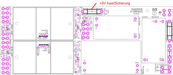
Zusätzlich verfügt das A-100PSU3 über eine
separate Sicherung für +5V (d.h. im Sekundärkreis). Falls nur die
+5V nicht vorhanden sind, hat mit großer Wahrscheinlichkeit diese Sicherung
angesprochen (auf Grund einer Überlast,
eines Kurzschlusses, einem defekten Modul o.ä.).
Die Sicherung befindet sich direkt auf Leiterplatte des A-100PSU3 in der Nähe
der vier Flachstecker für den +5V-Anschluss. Die untenstehende Abbildung zeigt
die Lage der 5V-Sicherung.
Um die Sicherung wechseln zu können, muss die Netzteilabdeckung entfernt
werden. Diese ist mit 2 Schrauben (Netzabdeckung für ein PSU3) oder 4 Schrauben
(Netzabdeckung für zwei PSU3) an der Gehäuse-Rückwand montiert. Unbedingt zuvor die Netzzuleitung
abziehen ! Es reicht nicht den Ausschalter zu betätigen !
Ab Werk ist eine Sicherung
mit 2A (flink) bestückt. Der Wert kann aber bei Bedarf auf bis zu 4A (flink)
erhöht werden, falls das wegen des Strombedarfs bei +5V erforderlich ist. Der
Wert dieser Sicherung ist unabhängig von der Netzspannung (d.h. er gilt für
Netzspannungen von 115V und 230V).
In addition the A-100PSU3 has a separate +5V
fuse in the secondary circuit available. If only the +5V are missing
probably this fuse is blown (because of overload,
short circuit, faulty module etc.). The fuse is located on the A-100PSU3 pc board near
the four +5V terminals. The sketch below shows the position of the 5V fuse.
To reach the fuse it
may be necessary to remove the power supply cover (2 or 4 screws).
It's essential
that the mains cable is disconnected before the cover is removed ! It's not
sufficient to operate the mains switch only !
From the factory 2A (fast) are installed.
The value
can be increased up to 4A (fast) if the total current consumption at +5V is more
than 2A. But this is
recommended only of really a higher current than 2A is required. The value of this fuse is independent from the mains
voltage (i.e. the same for 115V and 230V mains voltage).
Gehäuse mit A-100PSU2
/ Cases with A-100PSU2
verbaut bis Ende 2015 /
manufactured until end of 2015
| Gehäuse-Typ |
Case
Version |
Sicherungswerte
bei Netzspannung
230V
fuse values for 230V mains voltage |
Sicherungswerte
bei Netzspannung 115V
fuse values for 115V mains voltage |
maximale
Leistungsaufnahme
maximum power consumption |
| A-100G6 19"
Rahmen 6HE/84TE |
A-100G6
19" frame 6U/84HP |
400 mA |
800 mA |
50W |
| A-100P6
Kofferversion 6HE/84TE |
A-100P6
suitcase version 6U/84HP |
400 mA |
800 mA |
50W |
| A-100P9
Kofferversion 9HE/84TE |
A-100P9
suitcase version 9U/84HP |
400 mA |
800 mA |
50W |
| A-100PB Koffer-Unterbau
2x3HE/84TE |
A-100PB
suitcase base 2x3U/84HP |
400 mA |
800 mA |
50W |
| A-100LC6
Low-Cost Koffer 6HE/84TE |
A-100LC6
low cost suitcase 6U/84HP |
400 mA |
800 mA |
50W |
| A-100LC9
Low-Cost Koffer 9HE/84TE |
A-100LC9
low cost suitcase 9U/84HP |
400 mA |
800 mA |
50W |
| A-100LCB
Low-Cost Unterbau 2x3HE/84TE |
A-100LCB
low cost base 2x3U/84HP |
400 mA |
800 mA |
50W |
| A-100PMS6
Monster-Koffer 6HE/168TE |
A-100PMS6
monster suitcase 6U/168HP |
800
mA |
1.6 A |
100W |
| A-100PMS9
Monster-Koffer 9HE/168TE |
A-100PMS9
monster suitcase 9U/168HP |
800
mA |
1.6 A |
100W |
| A-100PMS12
Monster-Koffer 12HE/168TE |
A-100PMS12
monster suitcase 12U/168HP |
1,6 A |
3.15 A |
200W |
| A-100PMB
Monster-Unterbau 2x3HE/168TE |
A-100PMB
monster base frame 2x3U/168HP |
800 mA |
1.6 A |
100W |
| A-100LMS9
Low-Cost
Monster-Koffer 9HE/168TE |
A-100LMS9
low cost
monster suitcase 9U/168HP |
800
mA |
1.6 A |
100W |
| A-100LMB
Low-Cost
Monster-Unterbau 2x3HE/168TE |
A-100LMB
low cost
monster base frame 2x3U/168HP |
800
mA |
1.6 A |
100W |
Es sind unbedingt träge
Sicherungen 5x20 mm zu verwenden. Die Codierung für das Ansprechverhalten ist
üblicherweise auf der Sicherung mit dem Buchstaben F (fast
= schnell), M (medium = mittel) oder T (time
lag = träge) angegeben. Es muss eine Sicherung mit dem Code "T"
verwendet werden. Mittelträge oder flinke Sicherungen sind nicht
geeignet, da diese wegen der hohen Einschaltströme der Ringkerntransformatoren
sofort beim Einschalten ansprechen.
It's essential that time
lag (slow blow) fuses 5x20 mm have to be used ! Usually the type
of response is abbreviated by a character on the metallic ring of the
fuse: F (fast),
M (medium) or T (time lag = slow
blow). A fuse coded "T" has to be used ! Medium or fast fast fuses are unsuitable
and will blow. The reason for the time lag fuses is the high transient current
during power on that is ignored by the slow fuses. This transient current is
much higher for ring core/toroid transformer
than for normal transformers.
Gehäuse mit A-100PSU1
(A-100NT12) / Cases with A-100PSU1 (A-100NT12)
verbaut bis ca. 2003 / manufactured until about
2003
| Gehäuse-Typ |
Case
Version |
Sicherungswerte
bei Netzspannung
230V
fuse values for 230V mains voltage |
Sicherungswerte
bei Netzspannung 115V
fuse values for 115V mains voltage |
maximale
Leistungsaufnahme
maximum power consumption |
A-100G3 19"
Rahmen alte Version
(mit 650 mA Netzteil A-100NT12) |
A-100G3
19" frame old version
(with 650 mA
power supply A-100NT12) |
125 mA |
250 mA |
30W |
A-100G6 19"
Rahmen alte Version
(mit 650 mA Netzteil A-100NT12) |
A-100G6
19" frame old version
(with 650 mA
power supply A-100NT12) |
125 mA |
250 mA |
30W |
A-100G3 19"
Rahmen 3HE/84TE
alte Version
(mit 650 mA Netzteil A-100NT12) |
A-100G3
19" frame 3U/84HP
old version
(with 650 mA
power supply A-100NT12) |
125 mA |
250 mA |
30W |
Falls Sie noch einen der älteren Rahmen
oder Koffer mit dem alten Netzteil besitzen (A-100NT12, 650mA Ausgangsstrom,
produziert bis ca. 2001), so wird hier eine Sicherung mit 125 mA (230V) bzw. 250
mA (115V) eingesetzt. Es sind träge
Sicherungen 5x20 mm zu verwenden. Die Codierung für das Ansprechverhalten ist
üblicherweise auf der Sicherung mit dem Buchstaben F (fast
= schnell), M (medium = mittel) oder T (time
lag = träge) angegeben. Es muss eine Sicherung mit dem Code "T"
verwendet werden. Mittelträge oder flinke Sicherungen sind nicht geeignet.
If you still own an older A-100 frame or suitcase
with the old version of the power supply (A-100NT12, 650mA output current,
manufactured until about 2001) a fuse with 125 mA (230V) / 250 mA (115V) is
required. Time
lag (slow blow) fuses 5x20 mm have to be used ! Usually the type
of response is abbreviated by a character on the metallic ring of the
fuse: F (fast),
M (medium) or T (time lag = slow
blow). A fuse coded "T" has to be used ! Medium or fast fast fuses are unsuitable
and will blow.
Gehäuse A-100LC3 und A-100 DIY Kits /
Case A-100LC3 and A-100 DIY kits
Auch in den A-100 DIY-Kits 1 und 2, und im
A-100LC3 kommen
Sicherungen zum Einsatz. Diese werden jedoch hier zum Absichern des
Sekundärkreises verwendet (d.h. der Niederspannung). Es gibt hier zwischen den
verschiedenen Netzspannungen keinen Unterschied. Die untenstehenden Werte gelten
für die Steckertrafos bzw. Steckernetzteile, die von uns für die DIY-Kits
erhältlich sind. Falls andere Steckertrafos bzw. Steckernetzteile verwendet
werden, sind die Werte für die Sicherungen entsprechend anzupassen. Die in der
Tabelle angegebenen Werte entsprechen in diesem Fall den maximal zulässigen
Werten. Falls Trafos oder Steckernetzteile mit geringeren Leistungen verwendet
werden, sollten Sicherungen benutzt werden, die den Werten des Trafos bzw. des
Steckernetzteils entsprechen.
Even the A-100 DIY kits and the A-100LC3 contain fuses. There is no
difference between 115V and 230V for the fuse values as these fuses are used to
protect the secondary circuits of the supplies (i.e. the low voltages). The
specified values are valid for the transformers and wall outlet power supplies
that are available from us for the DIY kits. If other transformers or supplies
are used the values have to be changed depending on the specification of the
transformer or supply. In this case the values specified in the table are
maximum values. If a transformer or supply with lower power is used the fuse
values should be changed according to the specification of the transformer or
supply.
| DIY-Kit-Typ / type of
A-100 DIY kit |
Sicherungswerte (5x20mm) / fuse
values (5x20mm) |
| A-100LC3 |
2500mA/2.5A träge
/ 2500mA/2.5A time lag (slow blow) |
| A-100 DIY Kit #1 |
2500mA/2.5A träge
/ 2500mA/2.5A time lag (slow blow) |
| A-100 DIY Kit #2 |
2 x 500mA/0.5A träge / 2
x 500mA/0.5A time lag (slow blow) |
Wie
kann ich herausfinden ob in meinem A-100-Gehäuse ein Netzteil vom Typ A-100PSU3
oder A-100PSU2 eingebaut ist ?
Welcher
Typ von Netzteil in Ihrem A-100-Gehäuse verbaut wurde, können Sie an Hand des
Typenschildes oder Aufklebers an der Rückseite des Gehäuses neben dem
Netzeingang feststellen:
- Falls auf dem Typenschild oder Aufkleber
"100 - 240V" steht, so ist ein A-100PSU3 eingebaut.
- Falls auf dem Typenschild oder
Aufkleber "220 - 240V"
oder "100-120V" steht, so ist ein A-100PSU2 eingebaut.
Der wesentliche Unterschied besteht darin, dass
das A-100PSU3 einen sogenannten Weitbereichs-Eingang besitzt, der mit jeder
Netzspannung im Bereich von 100 bis 240V arbeitet. Dagegen ist das A-100PSU2 nur
für 230V (Toleranz-Bereich 220-240V) oder 115V (Toleranz-Bereich
110-120V) geeignet.
Zusätzlich können an Hand der Bilder der beiden Netzteile feststellen, welcher
Typ in Ihrem Gehäuse eingebaut ist: Sie finden die Bilder auf der A-100
Zubehör-Seite.
How
can I find out if my A-100 case contains a power supply A-100PSU3 or A-100PSU2 ?
The type of power supply can be identified by the
label at the rear panel next to the mains inlet.
- If the type plate or sticker says "100
- 240V" A-100PSU3 is installed.
- If the type plate or sticker says "220
- 240V" or "100-120V" A-100PSU2 is installed.
The main difference is that the A-100PSU3 has a
wide range mains input that can be used with any mains voltage in the range from
100 to 240V AC. A-100PSU2 is suitable only for 230V (range 220-240V) OR 115V
(range 110-120V).
In addition you can find out if an A-100PSU3 or PSU2 is installed by looking at
the pictures of the power supplies in the A-100
Accessories page
Reparaturen
in Eigenregie
Falls Sie etwas
Elektronikerfahrung besitzen und ein fehlerhaftes Modul nicht mehr unter die
Gewährleistung fällt, können Sie versuchen die Reparatur selbst
durchzuführen. Zu diesem Zweck dienen die folgenden Hinweise:
Bitte beachten Sie, dass die Gewährleistungsanspruch verloren geht, falls Sie
versuchen ein Modul selbst zu reparieren.
Als erstes empfehlen wir eine optische Kontrolle, um zu prüfen ob ein
mechanisches Problem vorliegt (z.B. mechanisch beschädigte oder verbogene
Bauteile, lose Teile, gebrochene Buchsen oder Schalter, unvollständig
aufgestecktes Busverbindungskabel, falls das Modul aus mehreren Leiterplatten
besteht: unvollständig aufgesteckte oder fehlende Verbindungskabel zwischen den
Leiterplatten etc.). Wir empfehlen auch auf Transistoren zu achten, ob diese
mechanisch beschädigt sind (z.B. ob sich die Lötaugen durch mechanischen Druck
von oben an der Unterseite abgelöst haben).
Falls keine mechanischen Fehler vorhanden sind, so sind defekte integrierte
Schaltung die häufigste Ursache für die Fehlfunktion eines Moduls -
insbesondere wenn das Modul versehentlich seitenverkehrt auf die Busplatine
aufgesteckt wurde. Das Ersetzen der integrierten Schaltungen löst in den
meisten Fällen das Problem. Leider lässt sich nicht vorhersagen, welche
Schaltung(en) defekt sind. Man muss daher der Reihe nach alle Schaltungen
ersetzen, um den Fehler zu finden. Die integrierte Schaltungen stecken in aller
Regel in entsprechenden Fassungen, so dass der Austausch relativ problemlos
durchgeführt werden kann. Beim Ersetzen einer Schaltung muss jedoch unbedingt
auf die Polung geachtet werden (meist eine Kerbe oder ein Markierungspunkt).
Falls dadurch das Problem nicht gelöst werden konnte, sind vermutlich andere
Halbleiter defekt und sollten ausgetauscht werden (z.B. Transistoren, Dioden
oder Spannungsregler). Hierzu ist allerdings ausreichend Erfahrung, sowie
passende Werkzeuge zum Auslöten und Einlöten erforderlich. Andernfalls kann
die Leiterplatte irreparabel beschädigt werden.
In mehr als 95% aller Fälle sollte damit das Problem behoben werden können.
Für die restlichen 5% sind detailliertes Elektronikwissen und spezielle
Messgeräte erforderlich, um den Fehler zu finden und zu beheben.
Falls Sie keinen Erfolg bei der Reparatur haben, so folgen Sie bitte den allgemeinen
Reparaturhinweisen. Falls Sie innerhalb der EU wohnen, können Sie das Modul
nach Rücksprache auch direkt zu Doepfer/Deutschland schicken.
DIY repair tips
If you are a bit experienced with electronics and
the faulty module is no longer covered by warranty you
may try to do the repair yourself. In this case we recommend to follow these DIY
repair notes:
Pay attention that warranty is void if your try to repair a module yourself. If
the module is still covered by warranty it has to be returned to the dealer
where you purchased it. Please do not try to repair the module yourself in this
case !
First of all have a look at the module to find out if there is an obvious
mechanical problem, e.g. mechanically bended or damaged electronic parts, loose
parts, broken sockets or switches, uncomplete connected bus cable, missing
cables between pc boards (provided that the module is made of several pcbs) and
so on. We recommend to have also a look at all transistors if they are
mechanically damaged and if the annular rings at the bottom of the pcb did not
come off (causing interruptions between the annular ring and the pcb track).
Next we recommend to replace all integrated circuits one after the other. In
most cases this will solve the problem. It's impossible to predict which circuit
has been damaged (especially if the module was plugged by mistake upside
down to the bus board). So one has to replace one after the other until the problem is
fixed.
If this does not solve the problem other semiconductors (mainly transistors and
voltage regulators) should be replaced.
In 95% of all cases this should fix the problem. For the remaining 5% a more
detailed knowledge and special measuring instruments are required to discover the
fault.
Without success the module has to be sent in to the dealer where you purchased
the module for repair. If the module was purchased second hand please contact the Doepfer
representative or a dealer in your country. If you stay within the EU (European
Union) you may send in the module for repair also to Doepfer directly. In this
case please look at the repair notes
which explain the repair processing in detail.
Adjustment procedure
for VCOs and VCFs
The following document explains detailed how to
adjust a VCO if necessary. All kind of VCOs are mentioned. The document is also
useful for the adjustment of VCFs: General_VCO_VCF_adjustment.pdf.
Pay attention that misadjusting a VCO or VCF is not covered by
warranty
Sind die A-100-Module in Form
von Bausätzen oder Leiterplatten erhältlich ? / Do you
offer the A-100 modules as kits or pc boards ?
Die A-100-Module sind nur als
komplett aufgebaute Module lieferbar. Bausätze, bestückte/unbestückte
Leiterplatten oder Frontplatten sind leider nicht erhältlich. Wir lassen die
A-100-Module schon seit vielen Jahren komplett außer Haus produzieren und
fertigen nicht mehr bei uns selbst. Unsere Produktionsfirmen liefert komplett
montierte und vorgetestete Module. Nur die Endkontrolle und Justierung der
Module findet noch bei uns statt.
A-100 modules are available
only as completely assembled units. Sorry - we do not offer kits,
assembled/unpopulated pc boards or front panels. The reason is that we do no
longer manufacture in-house but receive ready built and pre-tested modules from
our manufacturers. Only the final test and adjustment is still carried out
in-house.
Which modules
access CV and Gate of the A-100 bus ?
These modules are able to transmit CV and/or Gate signals to
the A-100 bus:
Usually jumpers are available that are used to
connect the CV and/or Gate output to the corresponding line of the A-100 bus
board. For details please refer to the information page or the user's manual of the module in question.
Pay attention that only one Gate or CV transmitter is
allowed for each bus segment. Otherwise a short circuit between two
outputs is made which may damage the modules. It is possible to divide each bus
board into two sections by removing the corresponding jumpers for CV and Gate in
the center of the bus board. These jumpers are used to connect the left and
right side of the CV or Gate lines of the bus board. If it is required that two
or more bus boards have available the same CV and/or Gate signals a special CV/Gate bus connection cable
(A-100BC = A-100 Bus Connector)) is necessary. This cable is made of two jumpers which are connected by
a wire. If the jumpers of the A-100BC are plugged to the pin headers in the
center of the two bus boards the CV and/or Gate lines of both bus boards are
connected.
These modules are able to receive CV and/or Gate signals from
the A-100 bus:
Usually a jumper is available that is used to
connect the CV or Gate input of the module to the corresponding line of the
A-100 bus board. For details please refer to the user's manual of the module in
question. In some cases the bus signal is added to the other inputs of the
module (e.g. A-111-1), in other cases normalling is used (i.e. the switching
contact of a socket at the front panel is connected to the bus signal). Other
modules may be connected to the CV and Gate signals of the bus too as described
on the A-100 DIY page -> Subsequent bus normalling of modules.
If more than 2-3 VCOs are supplied by the same CV
buffering of the CV is recommended. For this the modules A-185-1
Bus Access, A-185-2 Precision Adder or A-180-3
Buffered Multiple can be
used. The interfaces A-190-2, A-190-3
and A-190-4 feature buffered CV outputs. For these interfaces no additional CV buffers are
required. Buffering of Gate signals is usually not necessary.
Welche
Module nutzen die Signale CV und Gate des A-100-Busses
Folgende Module können CV und/oder Gate-Signale
an den A-100-Bus "senden":
Üblicherweise werden Steckbrücken (Jumper)
verwendet, um die CV- und/oder Gate-Leitung des betreffenden Moduls mit dem
A-100-Bus zu verbinden. Genauere Informationen finden Sie auf der Info-Seite
oder der Anleitung zu dem betreffenden Modul. Grundsätzlich gilt, dass nur
ein Gate- oder CV-Sender für jedes Bus-Segment gestattet ist.
Andernfalls würde ein Kurzschluss zwischen den CV- oder Gate-Ausgängen
hergestellt, der im ungünstigsten Fall eines oder beide Module zerstören kann.
Es ist möglich jede Busplatine nochmals in zwei Teile zu trennen. Hierzu
müssen die betreffenden Steckbrücken (je eine für Gate und CV) etwa in der
Mitte der Busplatine entfernt werden. Diese Steckbrücken dienen dazu, die CV-
bzw. Gate-Leitungen des linken und rechten Teils der Busplatine miteinander zu
verbinden. Ab Werk sind die Steckbrücken aufgesteckt. Falls zwei Busplatinen
mit den gleichen CV- oder Gate-Signalen versorgt werden sollen, so ist ein
spezielles Verbindungskabel (A-100BC = A-100 Bus Connector)
erforderlich. Dieses Kabel besteht aus zwei miteinander elektrisch verbundenen
Steckbrücken. Hierzu werden mit dem Kabel die CV und/oder Gate-Leitungen zweier
Busplatinen miteinander verbunden (über die CV/Gate-Stiftleisten in der Mitte
der Busplatinen).
Folgende Module können CV und/oder Gate-Signale
vom A-100-Bus "empfangen":
Üblicherweise werden Steckbrücken (Jumper)
verwendet, um die CV- und/oder Gate-Leitung des betreffenden Moduls mit dem
A-100-Bus zu verbinden. Genauere Informationen finden Sie auf der Info-Seite
oder der Anleitung zu dem betreffenden Modul. In einigen Fällen wird das vom
Bus kommende Steuersignal (CV oder Gate) zu den anderen Steuersignalen des
Moduls hinzu addiert (z.B. A-111-1), in anderen Fällen wird
"Normalisierung" verwendet (d.h. das vom Bus kommende Signal ist auf
den Schaltkontakt einer Buchse geführt und ist nur solange wirksam bis in die
betreffende Buchse ein Patch-Kabel eingesteckt wird). Es ist auch möglich
Module nachträglich mit CV und/oder Gate des A-100-Busses zu verbinden, falls
diese Funktion bei einem Modul nicht vorhanden ist. Nähere Informationen hierzu
finden Sie hier: A-100 DIY page -> Subsequent bus normalling of modules.
Falls mehr als 2-3 VCOs von der gleichen CV
angesteuert werden sollen, ist die Pufferung des CV-Signals zu empfehlen.
Andernfalls kann es zu Problemen im Tuning (speziell bei der Oktav-Reinheit)
kommen. Für diese Zwecke sind die Module A-185-1
Bus Access , A-185-2 Precision Adder oder A-180-3
Buffered Multiple geeignet. Die Midi-CV-Interface A-190-2,
A-190-3
und A-190-4 verfügen bereits über gepufferte
CV-Ausgänge. Bei diesen Modulen ist eine zusätzliche Pufferung der CV-Signale
nicht erforderlich.
Using the A-100 for
sound processing of external signals
The A-100 can be used to process any audio signal
(electric guitar, microphone, midi sound module, computer sound card, CD player,
tape-recorder , mp3 player ...). But one has to pay attention to some special features
of the A-100:
- The audio inputs of audio-processing A-100
modules (e.g. filters, VCAs, phaser, flanger, waveform processor, distortion,
wave multiplier, ring modulator, frequency shifter, spring reverb, panning
...) require a minimal level of about 1Vpp. Otherwise the signal-to-noise
ratio may become very poor. A higher level is no problem because virtually
each audio input is equipped with an attenuator to reduce the signal level. If the signal source does
not have the required level an external pre-amplifier is recommended.
Especially for low level sources like microphones or electric guitars an
external pre-amplifier is required.
- Additional controlling modules (e.g. low frequency
oscillators/LFOs, envelope generators/ADSRs, random voltage generators, slew
limiter, Theremin, Ribbon controller, Joy stick ...) are normally used to
control the parameters of the audio processing modules (e.g. filter
frequency, filter resonance, loudness, clipping level, wave multiples, phase shift, delay time ...).
- The A-100 uses 3,5 mm mono jack sockets and
has asymmetrical inputs and outputs. A special
cable or adaptor that converts the plug type of the sound source (e.g.
1/4" jack or RCA or XLR) to a 3,5 mm mono jack plug is required. For
1/4" jacks the A-181 can be used. We also
offer 3.5 mm to 1/4" adapter cables.
- The external input module A-119 is recommended
if the envelope of the signal (e.g. to control the filter frequency,
loudness or any other voltage controlled parameter of the A-100 modules) or
a gate signal (e.g. to trigger envelope generators) are desired. It has also
included an amplifier that may be used to increase the signal level of an
external signal. But it's not a "high-end" pre-amplifier and may
be not sufficient for high quality applications. In this case an external
high-end pre-amplifier is recommended.
- A list of all available A-100 modules can be found on
the A-100 modules overview page.
How to built a Theremin with modules from the A-100 modular system
The standard Theremin uses 2 antennas. One controls the pitch, the other one the
loudness. To reproduce the original Theremin four modules of the A-100 are required:
- one VCO (e.g. A-110) or A-143-9
- one VCA (e.g. A-130) or and
other VCA
- two Theremin modules (A-178)
- suitable case and power supply (A143-9 + A-130 + 2 x A-178
fit e.g. exactly into the A-100 miniature case A-100MC)
One Theremin (A-178) controls the pitch of the VCO (A-110
or A-143-9). The CV output of this
Theremin has to be connected to one of the pitch/tune CV inputs of the A-110 or
A-143-9. The second
Theremin (A-178) controls the loudness of the VCA. The CV output of this Theremin has to
be connected to one of the CV inputs of the A-130. The standard Theremin has a sine wave
output like the A-143-9. If you want to use the same waveform the sine output of the
A-110 has to be
connected to one of the the audio inputs of the VCA. But you may use another waveform too
or mix 2 of the waveforms using the 2 audio inputs of the A-130. The audio output of this
"Theremin" is the VCA output and is connected to your PA (mixer, amplifier,
effects unit ...).
If you do not want to use one of our base frames as case and power supply please refer
to the corresponding FAQ (power supply and case for A-100 modules).
But we recommend to use the Theremin modules A-178 for other applications as well. The
standard Theremin application described above is only one of many examples how to use the
A-178 modules. The A-178 modules can be used also to control the frequency of a VCF
(e.g. A-120), VC phaser (A-125), VC
effects (A-187-1), modulation speed (A-147),
modulation depth (LFO via VCA), attack or decay time (A-141,
A-142), panning
(A-134). As
the Theremin module A-178 is equipped with a gate output it can be used for switching
applications as well: e.g. start/stop, controlling a VC switch (A-150) or sequential
switch (A-151) or an envelop generator (e.g.
A-140).
Another important application is to use the Theremin module A-178 in combination with
the quantizer module A-156. The quantizer module can be used to "press" the CV
coming from the A-178 into a semitone, scale or chord grid. This means that only CVs
corresponding to semitone, major/minor scale or chords are generated.
Suggestions for a minimal Theremin system and a
combined Theremin/Sequencer system are available on
our web site.
I have problems with some cables
in combination with the older miniature jack sockets of the A-100
The 3.5 mm miniature jack sockets used in the A-100 system
before about 2002 have been very sensitive to the
diameter and shape of the jack plugs of the cables used to interconnect the modules. If
you have contact problems with older modules please try the following procedure:
- Disconnect the A-100 system from mains due to safety reasons
- Remove the module from the rack and disconnect the bus cable if necessary
- Insert the jack plug into the socket causing contact problems
- Press down the hollow of the "hot" contact very carefully using a slotted
screwdriver (see picture below)
- This should lead to a good contact between jack plug and jack socket
- If the result is not good enough repeat the procedure without inserted plug but pay
attention that the upper contact spring does not slip below the lower one. Use the
screwdriver very carefully !
- Connect the bus cable to the A-100 bus board (if removed)
- Assemble the module into the A-100 frame
- Connect the A-100 system to mains and turn the system on
-
Now the contact problem should no longer occur
P.S. During 2002 a new type of
jack sockets with stronger springs and so-called "curly rear
contacts" is used in the A-100. The problem described does not occur for modules manufactured later than
about end of 2002. B.t.w. this problem
occured for all manufacturers that used these sockets (S6PC, manufacturer:
Cliff/England) and not only the A-100 as sometimes claimed.
I have problems when
using the old version of the voltage controlled switches A-150 or A-151, or the S&H module
A-148 with voltages above +8V or
below -8V (e.g. clock, trigger or gate
signals)
The old versions of the voltage controlled switches A-150/A-151 and the S&H module A-148 are able to process voltages
only in the range -8V...+8V. Voltages less than -8V or more
than +8V will lead to malfunction of the module ! Please refer to the user's
manual of A-150, A-151 resp. A-148 (in the first issues of the manuals this information
was missing).
The technical reason is that for the VC switches used in the
A-150, A-151 and A-148 (CD4053) the max. voltage difference is about 16V. We placed
this voltage range symmetrical around GND so that voltages between -8V and +8V can be
processed. When it is desired to process voltages in the range 0...+12V at the
I/O resp. O/I in/outputs (e.g. clock, trigger or gate signals) the modification
described in the following is the solution. This modification allows to process voltages in
the range 0...+12V. Pay attention: in this case no longer negative
voltages (e.g. LFO or audio) can be processed. To modify the module A-150
resp. A-151 the internal
"+8V" signal has to be connected to +12V and the internal
"-8V" signal has to be connected to GND. The simplest solution is to
remove the +8V voltage regulator (78L08 = IC2 for A-150 resp. IC3 for A-151) and
replace it by a jumper (wire) that connects the internal +8V line to +12V. The resistor
R7 (1k5) for A-150 resp. R16 (1k5) for A-151 has to be replaced by a wire/jumper
so that the internal -8V line is connected to GND. All these electronic parts
are located near the bus connector. After these modifications the voltage range
for A-150 resp. A-151 becomes 0...+12V. The schematics of A-150 and A-151 are
enclosed below.
|
|
| A-150 schematics |
A-151 schematics |
P.S. Since spring 2004 a new version of the A-150 is
manufactured that covers the full A-100 voltage range -12V...+12V. Please look at
the A-150 information for details.
P.S. Since fall 2004 a new version of the A-151 is manufactured that
covers the full A-100 voltage range -12V...+12V. Please look at
the A-151 information for details.
P.S. Since summer 2005 a new version of the A-148 is manufactured that
covers the full A-100 voltage range -12V...+12V.
How to undo the
modifications of the A-155 ?
If the sequencer A-155 is connected to the sequencer controller A-154 the
former A-155 modifications have to be cancelled. The
following document describes how to undo the modifications: A155_Modifications_Undo.pdf
How to remove the
springs from the joystick of module A-174 ?
There are two possibilities:
- Bend very carefully the four metallic tongues of the corresponding
potentiometer that hold the end plate of the potentiometer in question. E.g.
a small screw driver could be used. Pay attention not to break off the
tongues. Then the end plate and the spring can be removed. Re-install the
end plate by bending back the four tongues. This can be done for both or
only one of the two potentiometers of the joystick.
- Another possibilitly is to compress the two ends of the spring and cut
with a suitable small cutting pliers without dismantling the potentiometer.
In this case the remnant of the spring remains in the potentiometer.
Pay attention that warranty is lost if the joystick is modified !
|
Die folgenden Hinweise
sind nur für Experten vorgesehen. Die hier beschriebenen Arbeiten dürfen nur von einem Fachmann
durchgeführt werden, der die erforderlichen Sicherheitsbestimmungen kennt und
die Einhaltung dieser auch gewährleistet.
The following notes are intended for experts onyl. Carrying out of works
described in these documents is allowed only for authorized
personnel who are familiar with all valid safety rules
|
Verdrahtung von Netzeingang,
Netzteil und Busplatinen beim A-100
Da hierbei auch Bauteile, Platinen oder Kabel vorkommen, die später
Netzspannung (230/115V) führen, dürfen diese Arbeiten nur von einem Fachmann
durchgeführt werden, der die erforderlichen Sicherheitsbestimmungen kennt und
die Einhaltung dieser auch gewährleistet. Von Laien dürfen diese
Arbeiten auf keinen Fall durchgeführt werden! Lebensgefahr !
Die entsprechenden Hinweise finden Sie als PDF-Dateien unter:
Wiring of the mains inlet, power supply and bus boards
As these works affects parts, pc boards and cables that conduct mains voltage
(230/115V) carrying out of these works is allowed only for experts or authorized
personnel who are familiar with all valid safety rules. Laymen are not
allowed to carry out these works ! Danger to Life.
The corresponding information is available as pdf files:
Ersatz des alten Netzteils (A-100NT12 / 650mA) durch das leistungsfähigere
Netzteil (A-100PSU2)
Da hierbei auch Bauteile, Platinen oder Kabel vorkommen, die später
Netzspannung (230/115V) führen, dürfen diese Arbeiten nur von einem Fachmann
durchgeführt werden, der die erforderlichen Sicherheitsbestimmungen kennt und
die Einhaltung dieser auch gewährleistet. Von Laien dürfen diese
Arbeiten auf keinen Fall durchgeführt werden! Lebensgefahr ! Die entsprechenden Hinweise finden Sie als
PDF-Datei unter A100_PSU2_D.PDF
Sinngemäß gelten die Hinweise auch beim Ersatz des A-100NT12 durch A-100PSU3
oder A-100PSU2 durch A-100PSU3.
Replacement
of the old power supply (A-100NT12 / 650mA) by the more
powerful supply (A-100PSU2)
As these works affects parts, pc boards and cables that conduct mains voltage
(230/115V) carrying out of these works is allowed only for experts or authorized
personnel who are familiar with all valid safety rules. Laymen are not
allowed to carry out these works ! Danger to Life.
The corresponding information is available as pdf file: A100_PSU2_E.PDF
In turn these notes are valid also for the replacement of A-100PSU2 by A-100PSU3
or A-100NT12 by A-100PSU3
Umstellung
der A-100 Netzteile (A-100NT12 oder A-100PSU2) auf eine andere
Netzspannung
Da hierbei auch Bauteile, Platinen oder Kabel vorkommen, die später
Netzspannung (230/115V) führen, dürfen diese Arbeiten nur von einem Fachmann
durchgeführt werden, der die erforderlichen Sicherheitsbestimmungen kennt und
die Einhaltung dieser auch gewährleistet. Von Laien dürfen diese
Arbeiten auf keinen Fall durchgeführt werden! Lebensgefahr ! Die entsprechenden Hinweise finden Sie als
PDF-Datei unter A100_PSU1_Voltage.pdf,
A100_PSU2_Voltage.pdf.
Modification
of the A-100 power supplies A-100NT12 and A-100PSU2 for
another mains voltage (115V or 230V)
As these works affects parts, pc boards and cables that conduct mains voltage
(230/115V) carrying out of these works is allowed only for experts or authorized
personnel who are familiar with all valid safety rules. Laymen are not
allowed to carry out these works ! Danger to Life.
The corresponding information is available as pdf files: A100_PSU1_Voltage.pdf,
A100_PSU2_Voltage.pdf
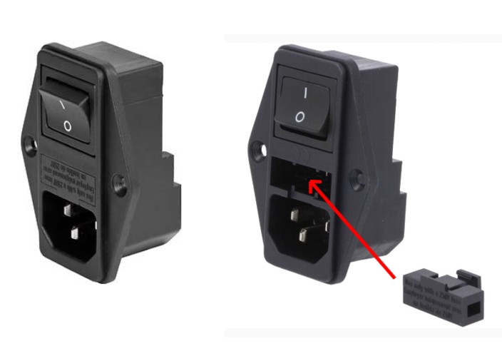